Hydrocarbons occupy a vital role in our life and continue to play an important role for many more years to come. We need to follow all technological innovations to continue our productivity standards to achieve our production targets. Let us extend our vision to achieve this mission.

Wednesday, June 30, 2010

Offshore Drilling

Drilling for natural gas offshore, in some instances hundreds of miles away from the nearest landmass, poses a number of different challenges over drilling onshore. The actual drilling mechanism used to delve into the sea floor is much the same as can be found on an onshore rig. However, with drilling at sea, the sea floor can sometimes be thousands of feet below sea level. Therefore, while with onshore drilling the ground provides a platform from which to drill, at sea an artificial drilling platform must be constructed.
Source: ChevronTexaco Corporation
Drilling offshore dates back as early as 1869, when one of the first patents was granted to T.F. Rowland for his offshore drilling rig design. This rig was designed to operate in very shallow water, but the anchored four legged tower bears much resemblance to modern offshore rigs. It wasn't until after World War II that the first offshore well, completely out of sight from land, was drilled in the Gulf of Mexico in 1947. Since then, offshore production, particularly in the Gulf of Mexico, has been very successful, with the discovery and delivery of a great number of large oil and gas deposits.

The Drilling Template
Since the land that is going to be drilled through cannot provide a base for offshore drilling as it does for onshore drilling, an artificial platform must be created. This artificial platform can take many forms, depending on the characteristics of the well to be drilled, including how far underwater the drilling target is. One of the most important pieces of equipment for offshore drilling is the subsea drilling template. Essentially, this piece of equipment connects the underwater well site to the drilling platform on the surface of the water. This device, resembling a cookie cutter, consists of an open steel box with multiple holes in it, dependent on the number of wells to be drilled. This drilling template is placed over the well site, usually lowered into the exact position required using satellite and GPS technology. A relatively shallow hole is then dug, in which the drilling template is cemented into place. The drilling template, secured to the sea floor and attached to the drilling platform above with cables, allows for accurate drilling to take place, but allows for the movement of the platform above, which will inevitably be affected by shifting wind and water currents.
In addition to the drilling template, a blowout preventer is installed on the sea floor. This system, much the same as that used in onshore drilling, prevents any oil or gas from seeping out into the water. Above the blowout preventer, a specialized system known as a 'marine riser' extends from the sea floor to the drilling platform above. The marine riser is designed to house the drill bit and drillstring, and yet be flexible enough to deal with the movement of the drilling platform. Strategically placed slip and ball joints in the marine riser allow the subsea well to be unaffected by the pitching and rolling of the drilling platform.
Moveable Offshore Drilling Rigs
There are two basic types of offshore drilling rigs: those that can be moved from place to place, allowing for drilling in multiple locations, and those rigs that are permanently placed. Moveable rigs are often used for exploratory purposes because they are much cheaper to use than permanent platforms. Once large deposits of hydrocarbons have been found, a permanent platform is built to allow their extraction. The sections below describe a number of different types of moveable offshore platforms.
A Drilling Barge
Source: California Department of Transportation
Drilling Barges
Drilling barges are used mostly for inland, shallow water drilling. This typically takes place in lakes, swamps, rivers, and canals. Drilling barges are large, floating platforms, which must be towed by tugboat from location to location. Suitable for still, shallow waters, drilling barges are not able to withstand the water movement experienced in large open water situations.
Jack-Up Rigs
A Jack-Up Rig
Source: National Oceanic and Atmospheric Administration
Jack-up rigs are similar to drilling barges, with one difference. Once a jack-up rig is towed to the drilling site, three or four 'legs' are lowered until they rest on the sea bottom. This allows the working platform to rest above the surface of the water, as opposed to a floating barge. However, jack-up rigs are suitable for shallower waters, as extending these legs down too deeply would be impractical. These rigs are typically safer to operate than drilling barges, as their working platform is elevated above the water level.
Submersible Rigs
Submersible rigs, also suitable for shallow water, are like jack-up rigs in that they come in contact with the ocean or lake floor. These rigs consist of platforms with two hulls positioned on top of one another. The upper hull contains the living quarters for the crew, as well as the actual drilling platform. The lower hull works much like the outer hull in a submarine - when the platform is being moved from one place to another, the lower hull is filled with air - making the entire rig buoyant. When the rig is positioned over the drill site, the air is let out of the lower hull, and the rig submerses to the sea or lake floor. This type of rig has the advantage of mobility in the water, however once again its use is limited to shallow water areas.
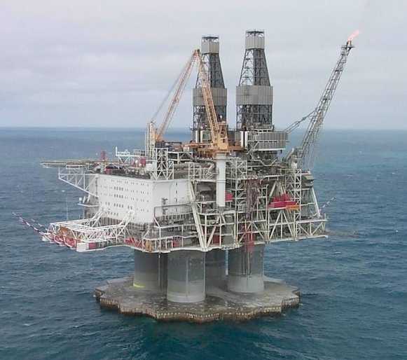
A Semisubmersible Rig
Source: Department of the Interior
Semisubmersible Rigs
Semisubmersible rigs are the most common type of offshore drilling rigs, combining the advantages of submersible rigs with the ability to drill in deep water. Semisubmersible rigs work on the same principle as submersible rigs; through the 'inflating' and 'deflating' of its lower hull. The main difference with a semisubmersible rig, however, is that when the air is let out of the lower hull, the rig does not submerge to the sea floor. Instead, the rig is partially submerged, but still floats above the drill site. When drilling, the lower hull, filled with water, provides stability to the rig. Semisubmersible rigs are held in place by huge anchors, each weighing upwards of ten tons. These anchors, combined with the submerged portion of the rig, ensure that the platform is stable and safe enough to be used in turbulent offshore waters. Semisubmersible rigs can be used to drill in much deeper water than the rigs mentioned above.

A Drillship in the Beaufort Sea
Source: Mining and Minerals Service
Drillships
Drillships are exactly as they sound: ships designed to carry out drilling operations. These boats are specially designed to carry drilling platforms out to deep-sea locations. A typical drillship will have, in addition to all of the equipment normally found on a large ocean ship, a drilling platform and derrick located on the middle of its deck. In addition, drillships contain a hole (or 'moonpool'), extending right through the ship down through the hull, which allow for the drill string to extend through the boat, down into the water. Drillships are often used to drill in very deep water, which can often be quite turbulent. Drillships use what is known as 'dynamic positioning' systems. Drillships are equipped with electric motors on the underside of the ships hull, capable of propelling the ship in any direction. These motors are integrated into the ships computer system, which uses satellite positioning technology, in conjunction with sensors located on the drilling template, to ensure that the ship is directly above the drill site at all times.
Offshore Drilling and Production Platforms
An Offshore Platform
Source: Duke Energy Gas Transmission Canada
As mentioned, moveable rigs are commonly used to drill exploratory wells. In some instances, when exploratory wells find commercially viable natural gas or petroleum deposits, it is economical to build a permanent platform from which well completion, extraction, and production can occur. These large, permanent platforms are extremely expensive, however, and generally require large expected hydrocarbon deposits to be economical to construct. Some of the largest offshore platforms are located in the North Sea, where because of almost constant inclement weather, structures able to withstand high winds and large waves are necessary. A typical permanent platform in the North Sea must be able to withstand wind speeds of over 90 knots, and waves over 60 feet high. Correspondingly, these platforms are among the largest structures built by man. There are a number of different types of permanent offshore platforms, each useful for a particular depth range.
This depiction of offshore drilling and completion platforms gives an idea of just how massive these offshore rigs can be. For reference, the fixed platform (the shallowest shown) is usually in no more than 1,500 feet of water - whereas the height of the Hoover Dam, from top to bottom, is less than half that, at just under 730 feet. Because of their size, most permanent offshore rigs are constructed near land, in pieces. As the components of the rig are completed, they are taken out to the drilling location. Sometimes construction or assembly can even take place as the rig is being transported to its intended destination.
Offshore Drilling Platforms
Source: MMS
Fixed Platforms
In certain instances, in shallower water, it is possible to physically attach a platform to the sea floor. This is what is shown above as a fixed platform rig. The 'legs' are constructed with concrete or steel, extending down from the platform, and fixed to the seafloor with piles. With some concrete structures, the weight of the legs and seafloor platform is so great, that they do not have to be physically attached to the seafloor, but instead simply rest on their own mass. There are many possible designs for these fixed, permanent platforms. The main advantages of these types of platforms are their stability, as they are attached to the sea floor there is limited exposure to movement due to wind and water forces. However, these platforms cannot be used in extremely deep water, it simply is not economical to build legs that long.
Compliant Towers
Compliant towers are much like fixed platforms. They consist of a narrow tower, attached to a foundation on the seafloor and extending up to the platform. This tower is flexible, as opposed to the relatively rigid legs of a fixed platform. This flexibility allows it to operate in much deeper water, as it can 'absorb' much of the pressure exerted on it by the wind and sea. Despite its flexibility, the compliant tower system is strong enough to withstand hurricane conditions. To learn more about compliant tower platforms, click here.
Seastar Platforms
Seastar platforms are like miniature tension leg platforms. The platform consists of a floating rig, much like the semisubmersible type discussed above. A lower hull is filled with water when drilling, which increases the stability of the platform against wind and water movement. In addition to this semisubmersible rig, however, Seastar platforms also incorporate the tension leg system employed in larger platforms. Tension legs are long, hollow tendons that extend from the seafloor to the floating platform. These legs are kept under constant tension, and do not allow for any up or down movement of the platform. However, their flexibility does allow for side-to-side motion, which allows the platform to withstand the force of the ocean and wind, without breaking the legs off. Seastar platforms are typically used for smaller deep-water reservoirs, when it is not economical to build a larger platform. They can operate in water depths of up to 3,500 feet. For an example of a Seastar platform in the Gulf of Mexico, click here.
A Floating Production System
Source: Minerals Management Service
Floating Production Systems
Floating production systems are essentially semisubmersible drilling rigs, as discussed above, except that they contain petroleum production equipment, as well as drilling equipment. Ships can also be used as floating production systems. The platforms can be kept in place through large, heavy anchors, or through the dynamic positioning system used by drillships. With a floating production system, once the drilling has been completed, the wellhead is actually attached to the seafloor, instead of up on the platform. The extracted petroleum is transported via risers from this wellhead to the production facilities on the semisubmersible platform. These production systems can operate in water depths of up to 6,000 feet.

A Tension Leg Platform
Source: Minerals Management Service
Tension Leg Platforms
Tension leg platforms are larger versions of the Seastar platform. The long, flexible legs are attached to the seafloor, and run up to the platform itself. As with the Seastar platform, these legs allow for significant side to side movement (up to 20 feet), with little vertical movement. Tension leg platforms can operate as deep as 7,000 feet.
Subsea System
Subsea production systems are wells located on the sea floor, as opposed to at the surface. Like in a floating production system, the petroleum is extracted at the seafloor, and then can be 'tied-back' to an already existing production platform. The well can be drilled by a moveable rig, and instead of building a production platform for that well, the extracted oil and natural gas can be transported by riser or even undersea pipeline to a nearby production platform. This allows one strategically placed production platform to service many wells over a reasonably large area. Subsea systems are typically in use at depths of 7,000 feet or more, and do not have the ability to drill, only to extract and transport.


Source

NaturalGas.org

Rotary Drilling

Rotary drilling uses a sharp, rotating drill bit to dig down through the Earth's crust. Much like a common hand held drill, the spinning of the drill bit allows for penetration of even the hardest rock. The idea of using a rotary drill bit is not new. In fact, archeological records show that as early as 3000 B.C., the Egyptians may have been using a similar technique. Leonardo Da Vinci, as early as 1500, developed a design for a rotary drilling mechanism that bears much resemblance to technology used today. Despite these precursors, rotary drilling did not rise in use or popularity until the early 1900's. Although rotary drilling techniques had been patented as early as 1833, most of these early attempts at rotary drilling consisted of little more than a mule, attached to a drilling device, walking in a circle! It was the success of the efforts of Captain Anthony Lucas and Patillo Higgins in drilling their 1901 'Spindletop' well in Texas that catapulted rotary drilling to the forefront of petroleum drilling technology.
While the concept for rotary drilling - using a sharp, spinning drill bit to delve into rock - is quite simple, the actual mechanics of modern rigs are quite complicated. In addition, technology advances so rapidly that new innovations are being introduced constantly. The basic rotary drilling system consists of four groups of components. The prime movers, hoisting equipment, rotating equipment, and circulating equipment all combine to make rotary drilling possible.
Prime Movers
The prime movers in a rotary drilling rig are those pieces of equipment that provide the power to the entire rig. Up until World War II, rotary rigs were traditionally powered by steam engines. Diesel engines became the norm after the war. Recently, while diesel engines still compose the majority of power sources on rotary rigs, other types of engines are also in use. Natural gas or gasoline engines are commonly used, as are natural gas or gasoline powered reciprocating turbines, which generate electricity on site. The resulting electricity is used to power the rig itself. Other rotary rigs may use electricity directly from power lines. Most rotary rigs these days require 1,000 to 3,000 horsepower, while shallow drilling rigs may require as little as 500 horsepower. Rotary rigs designed to drill in excess of 20,000 feet below surface may require much more than 3,000 horsepower. The energy from these prime movers is used to power the rotary equipment, the hoisting equipment, and the circulating equipment, as well as incidental lighting, water, and compression requirements not associated directly with drilling.
Working on an Onshore Drilling Rig
Source: Anadarko Petroleum Corporation
Hoisting Equipment
The hoisting equipment on a rotary rig consists of the tools used to raise and lower whatever other equipment may go into or come out of the well. The most visible part of the hoisting equipment is the derrick, the tall tower-like structure that extends vertically from the well hole. This structure serves as a support for the cables (drilling lines) and pulleys (draw works) that serve to lower or raise the equipment in the well. For instance, in rotary drilling, the wells are dug with long strings of pipe (drillpipe) extending from the surface down to the drill bit. If a drill bit needs to be changed, either due to wear and tear or a change in the subsurface rock, the whole string of pipe must be raised to the surface. In deep wells, the combined weight of the drillpipe, drill bit, and drill collars (thicker drillpipe located just above the bit) may be in excess of thousands of pounds. The hoisting equipment is used to raise all of this equipment to the surface so that the drill bit may be replaced, at which point the entire chain of drillpipe is lowered back into the well.
Positioning the Hoisting Equipment
Source: Anadarko Petroleum Corporation
The height of a rigs derrick can often be a clue as to the depth of the well being dug. Drillpipe traditionally comes in 30ft sections, which are joined together as the well is dug deeper and deeper. This means that even if a well is 20,000 feet deep, the drill string must still be taken out in 30 foot sections. However, if the derrick is tall enough, multiple joints of drillpipe may be removed at once, speeding up the process a great deal. Rotating Equipment
The rotating equipment on a rotary drilling rig consists of the components that actually serve to rotate the drill bit, which in turn digs the hole deeper and deeper into the ground. The rotating equipment consists of a number of different parts, all of which contribute to transferring power from the prime mover to the drill bit itself. The prime mover supplies power to the rotary, which is the device that turns the drillpipe, which in turn is attached to the drill bit. A component called the swivel, which is attached to the hoisting equipment, carries the entire weight of the drillstring, but allows it to rotate freely.
The drillpipe (which, when joined together, forms the drillstring) consists of 30ft sections of heavy steel pipe. The pipes are threaded so that they can interlock together. Drillpipe is manufactured to meet specifications laid out by the American Petroleum Institute (API), which allows for a certain degree of homogeneity for drillpipes across the industry. The drillpipe is a very heavy, strong pipe, but can be quite flexible when used in slant or horizontal drilling applications.
Below the drillpipe are drill collars, which are heavier, thicker, and stronger than normal drillpipe. The drill collars help to add weight to the drillstring, right above the bit, to ensure there is enough downward pressure to allow the bit to drill through hard rock. The number and nature of the drill collars on any particular rotary rig can be altered depending on the down hole conditions experienced while drilling.
Diamond Studded Drill Bits
Source: Sandia National Laboratory (left), DOE - National Energy Technology Laboratory
The drill bit is located at the bottom end of the drillstring, and is responsible for actually making contact with the subsurface layers, and drilling through them. The drill bit is responsible for breaking up and dislodging rock, sediment, and anything else that may be encountered while drilling. There are dozens of different drill bit types, each designed for different subsurface drilling conditions. Different rock layers experienced during drilling may require the use of different drill bits to achieve maximum drilling efficiency. It can be a long process to change bits, due to the fact that the whole drill string must be removed; but using the correct drill bit, or replacing a worn bit, can save a great deal of time during drilling. Drill bits are chosen given the underground formations expected to be encountered, the type of drilling used, whether or not directional drilling is needed, the expected temperatures underneath the Earth, and whether or not cores (for logging purposes) are required. There are four main types of drill bits, each suited for particular conditions.
  • Steel Tooth Rotary Bits are the most basic type of drill bit used today.
  • Insert Bits are steel tooth bits with tungsten carbide inserts.
  • Polycrystalline Diamond Compact Bits have polycrystalline diamond inserts attached to the carbide inserts found in Insert Bits.
  • Diamond Bits have industrial diamonds implanted in them, to drill through extremely hard rock formations. Diamond bits are forty to fifty times harder than traditional steel bits, and can thus be used to drill through extremely hard rock without dulling overly quickly.
In addition to these main types of drill bits, hybrid bits, combining the features of various types of bits, can be used. If core samples are required for logging purposes, core bits are designed to drill and obtain these samples. There are a great number of different designs for drill bits, including tricone roller bits, button bits, tapered bits, fishtail bits, and mill bits. Each of these bits has specifically designed drilling traits. The fishtail bit, for instance, is designed to enlarge the drill hole above the drill bit, and the mill bit is designed to mill away metal scraps or objects found in the well. The drill bit, in addition to being very useful, is also very expensive. It is thus up to the drilling engineer to ensure that the correct bit is used at the correct time, to allow for maximum drilling efficiency, with minimum wear and tear on the valuable bit.
Lowering the Bit and Drill Collar into the Well Hole
Source: NGSA
Circulating System
The final component of rotary drilling consists of the circulating system. There are a number of main objectives of this system, including cooling and lubricating the drill bit, controlling well pressure, removing debris and cuttings, and coating the walls of the well with a mud type-cake. The circulating system consists of drilling fluid, which is circulated down through the well hole throughout the drilling process.
Typically, liquid drilling fluids are used. The most common liquid drilling fluid, known as 'mud', may contain clay, chemicals, weighting materials, water, oil, or gases. 'Air drilling' is the practice of using gasses as the drilling fluid, rather than a liquid. Gases used include natural gas, air, or engine exhaust. Air drilling can significantly cut down on drilling time, as well as drilling fluid costs. The drilling fluid, much like the bit, is custom designed and chosen depending on what type of subsurface conditions are expected or experienced. For example, if drilling is occurring through underground salt formations, freshwater would not be used, as this would risk dissolving the subsurface salt. Similarly, if drilling near sources of fresh water, salt water would not be used for fear of contaminating the fresh water.
The drilling fluid chosen must have a number of properties to allow it to accomplish its tasks. It must be light and thin enough to circulate through the drill bit, cooling the bit as it drills as well as lubricating the moving parts. The fluid must be heavy enough to carry drill cuttings away from the bit and back to the surface, as well as control upward pressure that may be experienced in the well to prevent blowouts. The drilling fluid engineer ensures that the weight of the drilling fluid is greater than the upward pressure of escaping gas that may be encountered while drilling. In addition, the drilling fluid must be thick enough to coat the wellbore with a cake, which serves to temporarily seal the walls of the well until casing can be installed.
The circulating system consists of a starting point, the mud pit, where the drilling fluid ingredients are stored. Mixing takes place at the mud mixing hopper, from which the fluid is forced through pumps up to the swivel and down all the way through the drill pipe, emerging through the drill bit itself. From there, the drilling fluid circulates through the bit, picking up debris and drill cuttings, to be circulated back up the well, traveling between the drill string and the walls of the well (also called the 'annular space'). Once reaching the surface, the drilling fluid is filtered to recover the reusable fluid.
An Onshore Drilling Rig
Source: DOE - EREN
In addition to the fluid itself regulating downhole pressures encountered while drilling, a device known as the 'blowout preventer' is situated on the well casing below the deck of the rig. A blowout can occur when uncontrolled underground oil or gas pressure exerts more upward pressure than the drilling fluid itself can offset. The blowout preventer can consist of hydraulically powered devices that can seal off the well quickly and completely, preventing any potential for a well blowout should extreme downhole pressures be encountered. Pressure release systems are also installed to relieve the great pressure that can be experienced in a blowout situation.


Source

NaturalGas.org

Onshore Drilling

Onshore Drilling


Source: ChevronTexaco Corporation
Drilling into the Earth in the hopes of uncovering valuable resources is nothing new. In fact, the digging of water and irrigation wells dates back to the beginning of recorded history. At first, these wells were primarily dug by hand, then by crude stone or wood tools. Metallurgy brought about the use of iron and bronze tools to delve beneath the Earth's surface, and innovations led to more efficient ways of removing debris from the newly dug hole. The first recorded instance of the practice of 'drilling' holes in the ground came about around 600 B.C., when the Chinese developed a technique of repeatedly pounding bamboo shoots capped with metal bits into the ground. This crude technology was the first appearance of what is now known as 'percussion drilling'; a method of drilling that is still in use today. Much advancement has been made since these first bamboo drilling implements, with the realization of the value and increased demand for subsurface hydrocarbons. This section will cover the basics of modern onshore natural gas drilling practices.
There are two main types of onshore drilling. Percussion, or 'cable tool' drilling, consists of raising and dropping a heavy metal bit into the ground, effectively punching a hole down through the Earth. Cable tool drilling is usually used for shallow, low pressure formations. The second drilling method is known as rotary drilling, and consists of a sharp, rotating metal bit used to drill through the Earth's crust. This type of drilling is used primarily for deeper wells that may be under high downhole pressure.
Cable Tool Drilling
Cable tool, or percussion drilling is recognized by many as the first drilling method employed to dig wells into the Earth for the purpose of reaching petroleum deposits and water. This method is still in use in some of the shallow wells in the Appalachian Basin, although rotary drilling has taken over the bulk of modern drilling activities.
The basic concept for cable tool drilling consists of repeatedly dropping a heavy metal bit into the ground, eventually breaking through rock and punching a hole through to the desired depth. The bit, usually a blunt, chisel shaped instrument, can vary with the type of rock that is being drilled. Water is used in the well hole to combine with all of the drill cuttings, and is periodically bailed out of the well when this 'mud' interferes with the effectiveness of the drill bit.
Early Percussion Rigs in Pennsylvania - Late 1800's
Source: Office of Fossil Energy, DOE
Cable tool drilling has historically taken many forms. In the early days of percussion drilling, equipment was very crude compared to today's technology. The 'springpole' technique, used in the early 1800's, consisted of a flexible pole (usually a tree trunk) anchored at one end, and laying across a fulcrum, much like a diving board. The flexible pole, or springpole, would have a heavy bit attached at the loose end. In order to get the bit to strike the ground, workers would use their own body weight to bend the pole towards the ground, allowing the bit to strike rock. The tension in the pole would spring the bit free, should it become stuck in the ground. Much advancement has been made since these early percussion rigs. In fact, it was from cable tool drilling that one of the most important drilling advancements was made. In 1806, David and Joseph Ruffner were using the springpole technique to drill a well in West Virginia. In order to prevent their well from collapsing, they used hollow tree trunks to reinforce the sides of the well, and to keep water and mud from entering the well as they dug. They are credited as the first drillers to use a casing in their well - an advancement that made drilling much more efficient and easily accomplished. It is believed by many that 'Colonel' Drake's 1856 well achieved success due to the use of steel casing to reinforce the well. Drake's well was drilled using steam powered cable tool drilling methods.
A Modern, Mobile Cable Tool Drilling Rig
Source: Anadarko Petroleum Corporation
Innovations, such as the use of steam power in cable tool drilling, greatly increased the efficiency and range of percussion drilling. Conventional man-powered cable tool rigs were generally used to drill wells 200ft or less, while steam powered cable tool rigs, consisting of the familiar derrick design, had an average drilling depth of 400 to 500 feet. The deepest known well dug with cable tool drilling was completed in 1953, when the New York Natural Gas Corporation drilled a well to a depth of 11,145 ft


Source

NaturalGas.org.

Well Completion

Once a natural gas or oil well is drilled, and it has been verified that commercially viable quantities of natural gas are present for extraction, the well must be 'completed' to allow for the flow of petroleum or natural gas out of the formation and up to the surface. This process includes strengthening the well hole with casing, evaluating the pressure and temperature of the formation, and then installing the proper equipment to ensure an efficient flow of natural gas out of the well.
There are three main types of conventional natural gas wells. Since oil is commonly associated with natural gas deposits, a certain amount of natural gas may be obtained from wells that were drilled primarily for oil production. These are known as oil wells. In some cases, this "associated" natural gas is used to help in the production of oil, by providing pressure in the formation for the oils extraction. The associated natural gas may also exist in large enough quantities to allow its extraction along with the oil. Natural gas wells are wells drilled specifically for natural gas, and contain little or no oil.
Condensate wells are wells that contain natural gas, as well as a liquid condensate. This condensate is a liquid hydrocarbon mixture that is often separated from the natural gas either at the wellhead, or during the processing of the natural gas. Depending on the type of well that is being drilled, completion may differ slightly. It is important to remember that natural gas, being lighter than air, will naturally rise to the surface of a well. Because of this, in many natural gas and condensate wells, lifting equipment and well treatment are not necessary.
Completing a well consists of a number of steps; installing the well casing, completing the well, installing the wellhead, and installing lifting equipment or treating the formation should that be required. Click on the links below to learn about these aspects of the well completion process:
Well Casing
Installing well casing is an important part of the drilling and completion process. Well casing consists of a series of metal tubes installed in the freshly drilled hole. Casing serves to strengthen the sides of the well hole, ensure that no oil or natural gas seeps out of the well hole as it is brought to the surface, and to keep other fluids or gases from seeping into the formation through the well. A good deal of planning is necessary to ensure that the proper casing for each well is installed. Types of casing used depend on the subsurface characteristics of the well, including the diameter of the well (which is dependent on the size of the drill bit used) and the pressures and temperatures experienced throughout the well. In most wells, the diameter of the well hole decreases the deeper it is drilled, leading to a type of conical shape that must be taken into account when installing casing. To review the drilling of a natural gas well and the history of drilling practices, including casing, click here.
There are five different types of well casing. They include:
  • Conductor Casing
  • Surface Casing
  • Intermediate Casing
  • Liner String
  • Production Casing
Conductor Casing
Conductor casing is installed first, usually prior to the arrival of the drilling rig. The hole for conductor casing is often drilled with a small auger drill, mounted on the back of a truck. Conductor casing, which is usually no more than 20 to 50 feet long, is installed to prevent the top of the well from caving in and to help in the process of circulating the drilling fluid up from the bottom of the well. Onshore, this casing is usually 16 to 20 inches in diameter while offshore casing usually measures 30 to 42 inches. The conductor casing is cemented into place before drilling begins.
A Small Auger Drill
Source: USGS
Surface Casing
Surface casing is the next type of casing to be installed. It can be anywhere from a few hundred to 2,000 feet long, and is smaller in diameter than the conductor casing. When installed, the surface casing fits inside the top of the conductor casing. The primary purpose of surface casing is to protect fresh water deposits near the surface of the well from being contaminated by leaking hydrocarbons or salt water from deeper underground. It also serves as a conduit for drilling mud returning to the surface, and helps protect the drill hole from being damaged during drilling. Surface casing, like conductor casing, is also cemented into place. Regulations often dictate the thickness of the cement to be used, to ensure that there is little possibility of freshwater contamination.
Intermediate Casing
Intermediate casing is usually the longest section of casing found in a well. The primary purpose of intermediate casing is to minimize the hazards that come along with subsurface formations that may affect the well. These include abnormal underground pressure zones, underground shales, and formations that might otherwise contaminated the well, such as underground salt-water deposits. In many instances, even though there may be no evidence of an unusual underground formation, intermediate casing is run as insurance against the possibility of such a formation affecting the well. These intermediate casing areas may also be cemented into place for added protection.
Liner Strings
Liner strings are sometimes used instead of intermediate casing. Liner strings are commonly run from the bottom of another type of casing to the open well area. However, liner strings are usually just attached to the previous casing with 'hangers', instead of being cemented into place. This type of casing is thus less permanent than intermediate casing.
Production Casing
Production casing, alternatively called the 'oil string' or 'long string', is installed last and is the deepest section of casing in a well. This is the casing that provides a conduit from the surface of the well to the petroleum producing formation. The size of the production casing depends on a number of considerations, including the lifting equipment to be used, the number of completions required, and the possibility of deepening the well at a later time. For example, if it is expected that the well will be deepened at a later date, then the production casing must be wide enough to allow the passage of a drill bit later on.
Installing Well Casing
Source: ChevronTexaco Corporation
Well casing is a very important part of the completed well. In addition to strengthening the well hole, it also provides a conduit to allow hydrocarbons to be extracted without intermingling with other fluids and formations found underground. It is also instrumental in preventing blowouts, allowing the formation to be 'sealed' from the top should dangerous pressure levels be reached. For more technical information on blowouts and their prevention, click here. Once the casing has been set, and in most cases cemented into place, proper lifting equipment is installed to bring the hydrocarbons from the formation to the surface. Once the casing is installed, tubing is inserted inside the casing, from the opening well at the top, to the formation at the bottom. The hydrocarbons that are extracted run up this tubing to the surface. This tubing may also be attached to pumping systems for more efficient extraction, should that be necessary.
Completion
Well completion commonly refers to the process of finishing a well so that it is ready to produce oil or natural gas. In essence, completion consists of deciding on the characteristics of the intake portion of the well in the targeted hydrocarbon formation. There are a number of types of completions, including:
  • Open Hole Completion
  • Conventional Perforated Completion
  • Sand Exclusion Completion
  • Permanent Completion
  • Multiple Zone Completion
  • Drainhole Completion
The use of any type of completion depends on the characteristics and location of the hydrocarbon formation to be mined.
Open Hole Completion
Open hole completions are the most basic type and are only used in very competent formations, which are unlikely to cave in. An open hole completion consists of simply running the casing directly down into the formation, leaving the end of the piping open, without any other protective filter. Very often, this type of completion is used on formations that have been treated with hydraulic of acid fracturing.
Conventional Perforated Completion
Conventional perforated completions consist of production casing being run through the formation. The sides of this casing are perforated, with tiny holes along the sides facing the formation, which allows for the flow of hydrocarbons into the well hole, but still provides a suitable amount of support and protection for the well hole. The process of actually perforating the casing involves the use of specialized equipment designed to make tiny holes through the casing, cementing, and any other barrier between the formation and the open well. In the past, 'bullet perforators' were used, which were essentially small guns lowered into the well. The guns, when fired from the surface, sent off small bullets that penetrated the casing and cement. Today, 'jet perforating' is preferred. This consists of small, electrically ignited charges, lowered into the well. When ignited, these charges poke tiny holes through to the formation, in the same manner as bullet perforating.
Sand Exclusion Completion
Sand exclusion completions are designed for production in an area that contains a large amount of loose sand. These completions are designed to allow for the flow of natural gas and oil into the well, but at the same time prevent sand from entering the well. Sand inside the well hole can cause many complications, including erosion of casing and other equipment. The most common method of keeping sand out of the well hole are screening, or filtering systems. This includes analyzing the sand experienced in the formation and installing a screen or filter to keep sand particles out. This filter may either be a type of screen hung inside the casing, or adding a layer of specially sized gravel outside the casing to filter out the sand. Both of these types of sand barriers can be used in open hole and perforated completions.
Permanent Completion
Permanent completions are those in which the completion, and wellhead, are assembled and installed only once. Installing the casing, cementing, perforating, and other completion work is done with small diameter tools to ensure the permanent nature of the completion. Completing a well in this manner can lead to significant cost savings compared to other types.
Multiple Zone Completion
Multiple zone completion is the practice of completing a well such that hydrocarbons from two or more formations may be produced simultaneously, without mixing with each other. For example, a well may be drilled that passes through a number of formations on its way deeper underground, or alternately, it may be efficient in a horizontal well to add multiple completions to drain the formation most effectively. Although it is common to separate multiple completions so that the fluids from the different formations do not intermingle, the complexity of achieving complete separation is often a barrier. In some instances, the different formations being drilled are close enough in nature to allow fluids to intermingle in the well hole. When it is necessary to separate different completions, hard rubber 'packing' instruments are used to maintain separation.
Drainhole Completion
Drainhole completions are a form of horizontal or slant drilling. This type of completion consists of drilling out horizontally into the formation from a vertical well, essentially providing a 'drain' for the hydrocarbons to run down into the well. In certain formations, drilling a drainhole completion may allow for more efficient and balanced extraction of the targeted hydrocarbons. These completions are more commonly associated with oil wells than with natural gas wells.
The Wellhead
A Wellhead
Source: NETL - DOE
The wellhead consists of the pieces of equipment mounted at the opening of the well to regulate and monitor the extraction of hydrocarbons from the underground formation. It also prevents leaking of oil or natural gas out of the well, and prevents blowouts due to high pressure formations. Formations that are under high pressure typically require wellheads that can withstand a great deal of upward pressure from the escaping gases and liquids. These wellheads must be able to withstand pressures of up to 20,000 psi (pounds per square inch). The wellhead consists of three components: the casing head, the tubing head, and the 'christmas tree'.
The casing head consists of heavy fittings that provide a seal between the casing and the surface. The casing head also serves to support the entire length of casing that is run all the way down the well. This piece of equipment typically contains a gripping mechanism that ensures a tight seal between the head and the casing itself.
The 'Christmas Tree'
Source: NGSA
The tubing head is much like the casing head. It provides a seal between the tubing, which is run inside the casing, and the surface. Like the casing head, the tubing head is designed to support the entire length of the casing, as well as provide connections at the surface, which allow the flow of fluids out of the well to be controlled.
The 'christmas tree' is the piece of equipment that fits atop the casing and tubing heads, and contains tubes and valves that serve to control the flow of hydrocarbons and other fluids out of the well. It commonly contains many branches and is shaped somewhat like a tree, thus its name, christmas tree. The christmas tree is the most visible part of a producing well, and allows for the surface monitoring and regulation of the production of hydrocarbons from a producing well.
Lifting and Well Treatment
Once the well is completed, it may begin to produce natural gas. In some instances, the hydrocarbons that exist in pressurized formations will naturally rise up through the well to the surface. This is most commonly the case with natural gas. Since natural gas is lighter than air, once a conduit to the surface is opened, the pressurized gas will rise to the surface with little or no interference. This is most common for formations containing natural gas alone, or with a light condensate. In these scenarios, once the christmas tree is installed, the natural gas will flow to the surface on its own.
In order to more fully understand the nature of the well, a potential test is typically run in the early days of production. This test allows well engineers to determine the maximum amount of natural gas that the well can produce in a 24 hour period. From this, and other knowledge of the formation, the engineer may make an estimation on what the MER, or 'most efficient recovery rate' will be. The MER is the rate at which the greatest amount of natural gas may be extracted without harming the formation itself. Another important aspect of producing wells is the 'decline rate'. When a well is first drilled, the formation is under pressure and produces natural gas at a very high rate. However, as more and more natural gas is extracted from the formation, the production rate of the well decreases. This is known as the decline rate. Certain techniques, including lifting equipment and well stimulation, can increase the production rate of a well.
A Horse Head Pump
Source: ChevronTexaco Corporation
In some natural gas wells, and oil wells that have associated natural gas, it is more difficult to ensure an efficient flow of hydrocarbons up the well. The underground formation may be very 'tight', making the movement of petroleum through the formation and up the well a very slow and inefficient process. In these cases, lifting equipment or well treatment is required.
Lifting equipment consists of a variety of specialized equipment used to help 'lift' petroleum out of a formation. This is most commonly used to extract oil from a formation. Because oil is found as a viscous liquid, it takes some coaxing to extract it from underground. Various types of lifting equipment are available, but the most common lifting method is known as 'rod pumping'. Rod pumping is powered by a surface pump that moves a cable and rod up and down in the well, providing the lifting pressure required to bring the oil to the surface. The most common type of cable rod lifting equipment is the 'horse head' or conventional beam pump. These pumps are recognizable by the distinctive shape of the cable feeding fixture, which resembles a horse's head.
Well Treatment
Well treatment is another method of ensuring the efficient flow of hydrocarbons out of a formation. Essentially, this type of well stimulation consists of injecting acid, water, or gases into the well to open up the formation and allow the petroleum to flow through the formation more easily. Acidizing a well consists of injecting acid (usually hydrochloric acid) into the well. In limestone or carbonate formations, the acid dissolves portions of the rock in the formation, opening up existing spaces to allow for the flow of petroleum. Fracturing consists of injecting a fluid into the well, the pressure of which 'cracks' or opens up fractures already present in the formation. In addition to the fluid being injected, 'propping agents' are also used. These propping agents can consist of sand, glass beads, epoxy, or silica sand, and serve to prop open the newly widened fissures in the formation. Hydraulic fracturing involves the injection of water into the formation, while CO2 fracturing uses gaseous carbon dioxide. Fracturing, acidizing, and lifting equipment may all be used on the same well to increase permeability.
These techniques are mostly applicable to oil wells, but have also been used to increase the extraction rate for gas wells. Because it is a low-density gas under pressure, the completion of natural gas wells usually requires little more than the installation of casing, tubing, and the wellhead. Unlike oil, natural gas is much easier to extract from an underground formation. However, as deeper and less conventional natural gas wells are drilled, it is becoming more common to use stimulation techniques on gas wells.


Source


NaturalGas.org

Friday, June 18, 2010

Oil and gas well completion

The operations that prepare a well bore for producing oil or gas from the reservoir. The goal of these operations is to optimize the flow of the reservoir fluids into the well bore, up through the producing string, and into the surface collection system. See also: Oil and gas field exploitation; Oil and gas well drilling
Casing and cement

The well bore is lined (cased) with steel pipe, and the annulus between well bore and casing is filled with cement.
Properly designed and cemented casing prevents collapse of the well bore and protects fresh-water aquifers above the oil and gas reservoirs from becoming contaminated with oil and gas and the oil reservoir brine. Similarly, the oil and gas reservoir is prevented from becoming invaded by extraneous water from aquifers that were penetrated above or below the productive reservoir. See also: Aquifer
The casing string is made up of joints of steel pipe which are screwed together to form a continuous string as the casing is extended into the well bore. The common length of an individual joint is 30 ft (9 m). Such factors as the depth of the well, the pressure, temperature, and corrosivity of the fluids to be produced and those in the reservoirs that are to be cased off (behind pipe) are taken into account in specifying the diameter, wall thickness, strength, and chemical composition of the steel pipe for a particular casing job.
In deep wells, one or more intermediate strings of casing are set (Fig. 1) in order to cement off either high-pressure intervals which cannot be controlled by the weight of the drilling fluid, or low-pressure intervals into which large volumes of drilling mud may flow and result in lost circulation, preventing further controlled drilling. When drilling into a high-pressure formation, casing is frequently set on top of it in order to facilitate well control operations if a blowout appears to be imminent.
Casing detail; casing strings in an oil well.

Fig. 1  Casing detail; casing strings in an oil well.
'
In order to achieve its objectives, the casing must be securely sealed to the well bore itself with cement, although special formulations may be required for specific wells. For example, high-temperature formations or producing formations which will be extensively fractured will require cement that will not set too rapidly at high temperature or will not crack too badly as a result of the pressure shock of hydraulic fracturing, respectively. The cement is pumped down the casing and then on up into the annulus to a predetermined height. Cement returns (to the surface) are not universally required. The cement is mixed, pumped, and metered with highly specialized mobile equipment which is supplied by an appropriate service company. In order not to end up with the casing filled with cement, a specially designed plug is inserted after the required amount of cement has been pumped in and displaced with water until the plug hits the bottom of the casing string. The plug and some minor amount of cement will have to be drilled out after the cement has set.
Well bore–reservoir connection

The nature of the reservoir, evaluated from a core analysis, cuttings, or logs, or from experience with like productive formations, determines the type of completion to be used: barefoot, casing set through and then perforated, or a shop perforated or slotted liner.
In a barefoot completion, the casing is set just above the producing formation, and the latter is drilled out and produced with no pipe set across it (Fig. 2). Such a completion can be used for hard rock formations which are not friable and will not slough, and when there are no opportunities for producing from another, lower reservoir.
Diagram of barefoot completion.

Fig. 2  Diagram of barefoot completion.
'
Set-through and perforated completions are also employed for relatively well-consolidated formations from which the potential for sand production is small. However, the perforated completion is used when a long producing interval must be prevented from collapse, when multiple intervals are to be completed in the one borehole, or when intervening water sands within the oil-producing interval are to be shut off and the oil-saturated intervals selectively perforated. Perforations are made with bullets or shaped charges (jet perforation). The bullets are fired from a gun with multiple barrels, spaced at desired intervals, which is lowered into the hole on a wire line. An electric impulse detonates the bullets. The holes created by bullets are frequently lined with fused metal and mineral debris and as a result may offer some resistance to fluid influx. See also: Well logging
The charges used in jet perforating are similar to the shaped charges used in bazookas. The shaped charges are run into the hole on a glass gun which disintegrates.
A shop-fabricated liner is used for friable formations from which some of the formation sand may flow into the well bore. The passage of such sand into the well bore may cause scoring of the seats and valves in the pump and its consequent failure to be able to lift produced fluid; or it may result in accumulation of a sand plug in the lower joints of casing through which the flow of fluids would be impeded, or in erosion of surface valves and piping. The holes in the liner are designed to screen out any produced sand, and such liners are gravel-packed. A slurry of gravel is circulated (washed-in) down behind the liner, prior to setting the liner hanger (Fig. 3). The distribution of particle diameters in the gravel pack is chosen so that the pack is an effective screen for the reservoir sand. A prepacked gravel liner may also be used, but since a gap is left between the well bore and the liner, which may fill up with the fine silt that is carried with the produced fluids, it is generally preferable to use a washed-in gravel pack.
Liner-type completion; preperforated liner.

Fig. 3  Liner-type completion; preperforated liner.

Production

A string of steel tubing is lowered into the casing string and serves as the conduit for the produced fluids. The tubing may be hung from the well-head or supported by a packer set above the producing zone. The packer is used when it is desirable to isolate the casing string from the produced fluids because of the latter's pressure, temperature, or corrosivity, or when such isolation may improve production characteristics.
Artificial lift

The tops of wells from which fluids flow as a result of the indigenous reservoir energy are equipped with a manifold known as the Christmas tree (Fig. 4). However, only some reservoirs have sufficient pressure and sufficient gas in solution (which is released at the lower pressure existing in the well bore and therefore lowers the effective density of the fluid in the tubing) to permit natural flow to the surface. The reservoir fluids from other reservoirs and, after pressure depletion, even from those which initially flowed must be brought to the surface by one of several methods of artificial lift.
Typical layout of a Christmas tree manifold.

Fig. 4  Typical layout of a Christmas tree manifold.

The most common method is the use of a rod pump which is set near the bottom of the hole and operated by reciprocating sucker rods which are in turn attached to the walking beam on the surface (Fig. 5). The walking beam is driven by a motor, and by the use of suitable cams and cranks the beam's seesaw movement raises and lowers the sucker rod string. The cycle and stroke length of the sucker rods are adjustable. Tubing pumps attached to the bottom of the tubing string have a relatively high capacity, but the entire string must be pulled to repair a damaged pump. Insert pumps are set within the tubing. Because of their restricted diameter, they have a limited capacity for lifting reservoir fluids, but they have the advantage that they can be pulled and replaced with a wire line without pulling the entire tubing string. For deeper wells, hydraulic motors can be used for which the actuating fluid (crude oil) is pumped down the tubing and returns with the produced fluid up through the annulus. Wells which produce a large amount of fluid (both water and oil) can economically use a submerged centrifugal pump driven by an electric motor for which an electric cable is run down the annulus. See also: Centrifugal pump
Schematic diagram of most commonly used downhole pumps.

Fig. 5  Schematic diagram of most commonly used downhole pumps.

For deep wells which produce a significant amount of gas, gas lift can be employed in which some of the produced gas is compressed and returned to the casing-tubing annulus. A series of pressure-actuated valves inserted in the tubing string permits the gas to enter the string at various levels to lower the effective density of the fluids in the tubing and propel the fluids to the surface (Fig. 6). A plunger lift system to assist with unloading liquids can be easily installed inside tubing without the need to pull the tubing. Such systems are used to produce high-gas-oil-ratio (GOR) wells, water-producing gas wells, or very-low-bottom-hole-pressure oil wells (used with gas lift).
Schematic representation of operation of a gas lift string. (a) 
Oil level above first valve. (b) First...

Fig. 6  Schematic representation of operation of a gas lift string. (a) Oil level above first valve. (b) First valve open and gas entering tubing; oil level in casing/tubing annulus moving downward. (c) Oil level has moved downward, and each valve has closed as gas has entered the next lowest valve.

Multiple completion

In some geological provinces, several successive but separated intervals are productive of oil and gas. In some instances, the production from all the intervals may be commingled in a single well bore. However, if the properties of the reservoirs or their fluids are different, then commingling may be unacceptable because of the potential for cross flow between the individual reservoirs. Multiple completions in which the producing zones are separated by the use of packers and individual tubing string are then used (Fig. 7).
Schematic diagram of a multiple completion.

Fig. 7  Schematic diagram of a multiple completion.
Water problems

Excessive water production increases the cost of oil production since energy must be expended in lifting the water to the surface. Water production may also jeopardize the production of oil and gas by saturating the oil-productive interval with water. Such damage is more likely to occur in low-pressure formations or formations which contain water-sensitive clays that swell in an excess of water.
Water-exclusion methods

Water exclusion may be effected by the application of cements of various types. If it is determined that water is entering from the lower portion of a producing sand in a relatively shallow, low-pressure well, a cement plug may be placed in the bottom of the hole so that it will cover the oil-water interface of the reservoir. This technique is called laying in a plug and may be accomplished by placing the cement with a dump-bottom bailer on a wire line or by pumping cement down the drill pipe or tubing. For deeper, higher-pressure, or more troublesome wells, a squeeze method is used. Squeeze cementing is the process of applying hydraulic pressure to force a cement into an exposed formation or through openings in the casing or liner. It is also used for repairing casing leaks; isolating producing zones prior to perforating for production; remedial or secondary cementing to correct a defective condition, such as channeling or insufficient cement on a primary cement job; sealing off a low-pressure formation that causes lost circulation of drilling fluids; and abandoning depleted producing zones to prevent migration of formation effluent and to reduce possibilities of contaminating other zones or wells.
The squeeze tool is a packer-type device designed to isolate the point of entry between or below packing elements. The tool is run into the hole on drill pipe or tubing, and the cement is squeezed out between or below these confining elements into the problem area. The well is then recompleted. It may be necessary to drill the cement out of the hole and reperforate, depending upon the outcome of the job performed in the squeeze process.
Water-exclusion plug back

Simple water shutoff jobs in shallow, deep, or high-pressure wells may also be performed in multizone wells in which the lower producing interval is depleted or the remaining recoverable reserves do not justify recompletion.
Here, water may be excluded by placing a packer-type plug above the interval, then producing formations that are already open or perforating additional intervals that may be present higher up the hole.
Production stimulation

Production may be impaired from a well bore as a result of drilling-mud invasion or of accumulation of clays and fine silts carried by the producing fluids to the borehole, or the lithology of the formation itself may have a naturally low permeability to reservoir fluids. Since the permeability to fluids of the formation within the first few feet of the well bore has an exponential effect on limiting the influx of fluid, the productivity of a well can frequently be increased manyfold by increasing the permeability of this element of the reservoir or removing the skin just at the face of the producing interval. This is accomplished by acidization and fracturing, and in some instances by the use of surfactants, solvents, and explosives. Specialized service companies conduct the work by using their own specially designed equipment.
Acidizing

Inhibited hydrochloric acid contains a chemical additive (an inhibitor) which prevents the acid from attacking steel. In this way the acid can be used for dissolving carbonates, oxides, and other compounds without fear of it attacking the well's steel tubulars. This formulation is used to dissolve limestone and dolomitic matrices and thus enlarge the flow channels in production-impaired reservoirs. Hydrochloric acid is also used to shrink and disperse sheaths of drilling mud on the well bore and to dissolve calcareous cements, which results in larger channels through which fluids can flow to the well bore.
Hydrofluoric acid (released by injecting a mixture of hydrochloric acid and a soluble fluoride salt) is sometimes used in sandstone reservoirs to dissolve and disperse drilling mud that has invaded the reservoir.
Fracturing

Formation fracturing is a hydraulic process aimed at the parting of the formation. Vertical fractures most frequently occur. Horizontal fracturing occurs only in relatively shallow formations, in formations where the major tectonic stress is horizontal, or in relatively plastic formations. The fracturing fluid is injected into the well, and the pressure is raised to maintain a given flow rate until formation breakdown occurs. Injection is continued with a slurry of a selected grade of sand or gravel or particles of other material (such as sintered bauxite or ceramic beads). These particles prop the fracture open after the hydraulic pressure is released. Crude oil, acid, and a variety of gelled liquids are used as fracturing fluids. The propping material guarantees that there will be a high-permeability path into the well bore, and the nature of fluid flow in the vicinity of the well bore is changed to being predominantly linear rather than radial with an associated decrease in pressure drop (or higher flow rate at the same pressure drop).
Other stimulation techniques

Explosives were the first means used to stimulate oil and gas production. However, this technique has largely been supplanted by more effective and safe fracturing and acidizing technology.
Solvents are used when the substances believed to be inhibiting production are asphaltenes, waxes, and emulsions stabilized by such organic materials. Surfactants are frequently used with the solvents to aid in the dispersion of the sediments. Surfactants or alcohols (for example, methanol) are also used alone when the cause of impairment is believed to be a high saturation of water that has accumulated in the reservoir near the well bore.
Sand consolidation

Sand exclusion techniques using liners and gravel packs are not perfect, and therefore technology has been developed that attempts to consolidate friable formations. The consolidating medium must be capable of cementing the grains together without significantly reducing the permeability of the reservoir to fluid flow. Epoxy and phenolic resins have been developed for such purposes; some techniques use thermally deposited nickel metal and precipitated aluminum oxides. However, liners with properly designed gravel packs continue to be the most economical and useful technique for sand control.
Coiled tubing

Many of the well completion or workover techniques can be implemented with a coiled tubing unit that can greatly reduce costs. Instead of moving in a completion rig to lower or pull tubing, a coiled tubing unit may be moved next to the wellhead. With such a unit, instead of having to connect and disconnect stands of tubing, a continuous length of tubing may be uncoiled or coiled into the borehole by using a large spool. In this way, numerous operations may be performed on a well such as acidizing, setting and retrieving bridge plugs or packers, cementing, cleaning out the hole, and even light-duty or slim-hole drilling. A wide variety of remedial operations may be performed. See also: Petroleum reservoir engineering
Todd M. Doscher
R. E. Wyman
Bibliography

  • J. Algeroy, Equipment and operation of advanced completions in the M-15 Wytch Farm mulitlateral well, presented at the 2000 Anuual Technical Conference and Exhibition (Dallas), Pap. SPE 62951, October 1-4, 2000
  • G. Botto et al., Innovative remote controlled completion for Aquila Deepwater Challenge, 1996 SPE European Petroleum Conference (Milan), Pap. SPE 36948, October 22-24, 1996
  • R. A. Dawe and Alan G. Lucas (eds.), Modern Petroleum Technology, vols. 1 and 2, 6th ed., 2000
  • M. J. Economides, A. D. Hill, and C. Ehlig-Economides, Petroleum Production Systems, 1993
  • N. J. Hyne, Nontechnical Guide to Petroleum Geology, Exploration, Drilling and Production, 2d ed., 2001
  • V. B. Jackson, Intelligent completion technology improves economics in the Gulf of Mexico, Amer. Oil Gas Rep., June 2000
  • D. E. Johnson, Reliable and completely interventionless intelligen completion technology: Application and field study, 2002 Offshore Technology Conference (Houston), Pap. OTC 14252, May 6-9, 2002

Source

Access Science

Thanks for visiting the site and your interest in oil and gas drilling

free counters