Sunday, May 23, 2010
Cementing
Source:
Schlumberger
Saturday, May 22, 2010
Engineering in drilling and oil well
Many engineers develop new products. During the process, they consider several factors. For example, in developing an industrial robot, engineers specify the functional requirements precisely; design and test the robot's components; integrate the components to produce the final design; and evaluate the design's overall effectiveness, cost, reliability, and safety. This process applies to the development of many different products, such as chemicals, computers, powerplants, helicopters, and toys.
In addition to their involvement in design and development, many engineers work in testing, production, or maintenance. These engineers supervise production in factories, determine the causes of a component’s failure, and test manufactured products to maintain quality. They also estimate the time and cost required to complete projects. Supervisory engineers are responsible for major components or entire projects. (See the statement on engineering and natural sciences managers elsewhere in the Handbook.)
Engineers use computers extensively to produce and analyze designs; to simulate and test how a machine, structure, or system operates; to generate specifications for parts; to monitor the quality of products; and to control the efficiency of processes. Nanotechnology, which involves the creation of high-performance materials and components by integrating atoms and molecules, also is introducing entirely new principles to the design process.
Most engineers specialize. Following are details on the 17 engineering specialties covered in the Federal Government's Standard Occupational Classification (SOC) system. Numerous other specialties are recognized by professional societies, and each of the major branches of engineering has numerous subdivisions. Civil engineering, for example, includes structural and transportation engineering, and materials engineering includes ceramic, metallurgical, and polymer engineering. Engineers also may specialize in one industry, such as motor vehicles, or in one type of technology, such as turbines or semiconductor materials.
In that in particular we take an inlook in petroleum engineering/drilling engineering. Petroleum engineers design methods for extracting oil and gas from deposits below the earth. Once these resources have been discovered, petroleum engineers work with geologists and other specialists to understand the geologic formation and properties of the rock containing the reservoir, to determine the drilling methods to be used, and to monitor drilling and production operations. They design equipment and processes to achieve the maximum profitable recovery of oil and gas. Because only a small proportion of oil and gas in a reservoir flows out under natural forces, petroleum engineers develop and use various enhanced recovery methods, including injecting water, chemicals, gases, or steam into an oil reservoir to force out more of the oil and doing computer-controlled drilling or fracturing to connect a larger area of a reservoir to a single well. Because even the best techniques in use today recover only a portion of the oil and gas in a reservoir, petroleum engineers research and develop technology and methods for increasing the recovery of these resources and lowering the cost of drilling and production operations.
Source
Bureau of labor statistics
Christmas tree (oil well)


Overview
Note that a tree and wellhead are separate pieces of equipment not to be mistaken as the same piece. A wellhead must be present in order to utilize a Christmas tree and a wellhead is used without a Christmas tree during drilling operations, and also for riser tie-back situations which would then have a tree included at riser top. Producing surface wells that require pumps (pump jacks, nodding donkeys, and so on) frequently do not utilize any tree due to NO pressure containment requirement.
Tree complexity has increased over the last few decades. They are frequently manufactured from blocks of steel containing multiple valves rather than made from multiple flanged valves. This is especially true in subsea applications where the resemblance to Christmas trees no longer exists given the frame and support systems into which the main valve block is integrated.
It is common to identify the type of tree as either "subsea tree" or "surface tree". Each of these classifications has a number or varieties within them. Examples of subsea include conventional, dual bore, mono bore, TFL (through flow line), horizontal, mudline, mudline horizontal, side valve, and TBT (through bore tree) trees.
The primary function of a tree is to control the flow into or out of the well, usually oil or gas. A tree often provides numerous additional functions including chemical injection points, well intervention means, pressure relief means (such as annulus vent), tree and well monitoring points (such as pressure, temperature, corrosion, erosion, sand detection, flow rate, flow composition, valve and choke position feedback, connection points for devices such as down hole pressure and temperature transducer (DHPT).
When the operator, well, and facilities are ready to produce and receive oil or gas, valves are opened and the release of the formation fluids is allowed to flow into and through a pipeline. The pipeline then leads to a processing facility, storage depot and or other pipeline eventually leading to a refinery or distribution center (for gas). Subsea wells and thus trees usually flow through flowlines to a fixed or floating production platform or to a storage vessel (known as a floating storage offloading vessel (FSO), or floating processing unit (FPU), or floating production and offloading vessel or FPSO or other combination of structures).
A tree may also be used to control the injection of gas or water injection application on a producing or non-producing well in order to sustain economic "production" volumes of oil from other well(s) in the area (field).
On producing wells, injection of chemicals or alcohols or oil distillates to prevent and or solve production problems (such as blockages) may be used. Functionality may be extended further by using the control system on a subsea tree to monitor, measure, and react to sensor outputs on the tree or even down the well bore.
The control system attached to the tree controls the downhole safety valve (scssv, dhsv, sssv) while the tree acts as an attachment and conduit means of the control system to the downhole safety valve.
Christmas trees are used on both surface and subsea wells (current technical limits are up to around 3000 metres and working temperatures of -50°F to 350°F with a pressure of up to 15,000 psi). The deepest installed subsea tree is in the Gulf of Mexico at approximately 9000 feet.
Valves
Subsea and surface trees have a large variety of valve configurations and combinations of manual and/or actuated (hydraulic or pneumatic) valves. Examples are identified in API Specifications 6A and 17D.
A basic surface tree consists of two or three manual valves (usually gate valves because of their strength).
A typical sophisticated surface tree will have at least four or five valves, normally arranged in a crucifix type pattern (hence the endurance of the term "Christmas tree"). The two lower valves are called the master valves (upper and lower respectively) because they lie in the flow path, which well fluids must take to get to surface. The lower master valve will normally be manually operated, while the upper master valve is often hydraulically actuated, allowing it to be a means of well control while an actuated wing valve is normally the primary well remotely (from control room or control panel) controlled valve. Hydraulic tree wing valves are usually built to be fail safe closed, meaning they require active hydraulic pressure to stay open.
The right hand valve is often called the flow wing valve or the production wing valve, because it is in the flowpath the hydrocarbons take to production facilities (or the path water or gas will take from production to the well in the case of injection wells).
The left hand valve is often called the kill wing valve. It is primarily used for injection of fluids such as corrosion inhibitors or methanol to prevent hydrate formation. In the North Sea, it is called the non-active side arm (NASA). It is typically manually operated.
The valve at the top is called the swab valve and lies in the path used for well interventions like wireline and coiled tubing. For such operations, a lubricator is rigged up onto the top of the tree and the wire or coil is lowered through the lubricator, past the swab valve and into the well. This valve is typically manually operated.
Some trees have a second swab valve, the two arranged one on top of the other. The intention is to allow rigging down equipment from the top of the tree with the well flowing while still preserving the Two barrier rule. With only a single swab valve, the upper master valve is usually closed to act as the second barrier, forcing the well to be shut in for a day during rig down operations. However, avoiding delaying production for a day is usually too small a gain to be worth the extra expense of a having a christmas tree with a second swab valve.
Subsea trees are available in either vertical or horizontal configurations with further speciality available such as dual bore, monobore, concentric, drill-through, mudline, guidlineless or guideline. Subsea trees may range in size and weight from a few tons to approximately 70 tons for high pressure, deepwater (>3000 feet) guidelineless applications. Subsea trees contain many additional valves and accessories compared to Surface trees. Typically a subsea tree would have a choke (permits control of flow), a floline connection interface (hub, flange or other connection), subsea control interface (direct hydraulic, electro hydraulic, or electric) and sensors for gathering data such as pressure, temperature, sand flow, erosion, multiPhase flow, single phase flow such as water or gas.
Source:
Wikipedia
Thursday, May 20, 2010
Blowout preventer

A blowout preventer (BOP) is a large valve that can seal off at the surface wellhead a well being drilled or worked over. During drilling or well interventions, the valve may be closed if pressure from an underground formation causes fluids such as oil or natural gas to enter the wellbore and threaten the rig. By closing this valve (usually operated remotely via hydraulic actuators), the drilling crew can prevent undesired fluid flow, thus helping to regain control of the wellbore. Once this is accomplished, often the drilling mud density within the hole can be increased until adequate fluid pressure is placed on the influx zone, and the BOP can be opened for operations to resume. The invention and use of BOPs were instrumental in the ending of oil gushers, which were dangerous and costly.
Use

BOPs come in a variety of styles, sizes and pressure ratings, and usually several individual units comprise a BOP stack. Blind rams are designed to close an open wellbore. Pipe rams seal around tubular components in the well (drill pipe, casing, tubing, or coiled tubing). Shear-seal BOPs are fitted with hardened steel shearing surfaces that can actually cut through drill pipe and tool strings, if all other barriers fail. Since BOPs are important for the safety of the crew, as well as the drilling rig and the wellbore itself, BOPs are regularly inspected, tested and refurbished. Tests vary from daily test of functions of critical wells to monthly or less frequent testing of wells with low likelihood of control problems.[1] Any of these BOPs may be installed underwater, normally with two hydraulic actuators.
Deepwater Horizon blowout
After the Deepwater Horizon drilling rig explosion on April 20, 2010, the blowout preventer should have activated itself automatically to avoid an oil spill in the Gulf of Mexico. Underwater robots were sent to manually activate the mechanism's switch, to no avail. As of May 2010[update] it is unknown why it failed.[2] BP representatives suggested that the preventer could have suffered an hydraulic leak.[3] Gamma-ray imaging of the preventer conducted on May 12 and May 13, 2010 showed that the preventer's internal valves were partially closed and were restricting the flow of oil. Whether the valves closed automatically during the explosion or were shut manually by ROV work is unknown.[3]
Types
BOPs come in two types, ram and annular. Both types are usually used together in drilling rig BOP stacks.
Ram BOPs utilize several sets of horizontally opposed hydraulic rams that can be fitted out to 1) close around the drill string, 2) shear through the drill string and then seal, or 3) close off a wellbore when no drill pipe or tubing is in it. The ram BOP was invented by James Smither Abercrombie and Harry S. Cameron in 1922, and was brought to market in 1924.[4]
An annular BOP, also known as a spherical BOP, utilizes a hemispherical piece of rubber reinforced with steel. Unlike a ram BOP, which closes with a sharp horizontal motion, an annular BOP closes around the drill string in a smooth simultaneous upward and inward motion. The geometry of this movement reduces internal stresses and friction between the BOP body and the sealing element, resulting in a longer field life with less maintenance. The annular design also allows a much lower operating pressure, reducing the number of hydraulic accumulators necessary and thereby reducing cost and complexity of the operation. It was invented by Granville Sloan Knox in 1946; a U.S. patent for it was awarded in 1952.[5]
Actuation methods
When rigs are drilling on land or in very shallow water where the wellhead is above the water line, BOPs are activated by hydraulic pressure from a remote accumulator. Several control stations will be mounted around the rig.
In deeper offshore operations with the wellhead on the sea floor, there are five primary means that a BOP may be activated. The means are
- automatic, based on excessive pressure;
- automatic, based on excessive flow;
- remotely by an electrical command from the surface through a cable;
- manually, based on external movement of a valve lever done underwater, or
- acoustically, based on a modulated/encoded pulse of sound transmitted by an underwater transducer.
Of these methods, general requirements in the United States were drawn to require only the first four. Specific requirements for permitting individual wells along the U.S. coastline may also call for acoustic actuation. General requirements of other nations, including Brazil, were drawn to require this method. BOPs featuring this method may cost as much as US$500,000 more than those that omit the feature.
The 2009 Minerals Management Service permitting of Deepwater Horizon in the Macondo Prospect did not require acoustic actuation.
Source
Wikipedia
Horizontal drilling
History

Many prerequisites enabled this suite of technologies to become productive. Probably the first requirement was the realization that oil wells (or water wells, but since they are shallower, most development was in the oil industry) are not necessarily vertical. This realization was quite slow, and did not really grasp the attention of the oil industry until the late 1920s when there were several lawsuits alleging that wells drilled from a rig on one property had crossed the boundary and were penetrating a reservoir on an adjacent property. Initially, proxy evidence such as production changes in pre-existing wells was accepted, but such cases fueled the development of small diameter tools capable of surveying wells during drilling.
Measuring the inclination of a wellbore (its deviation from the vertical) is comparatively simple, requiring only a pendulum. Measuring the azimuth (direction with respect to the geographic grid in which the wellbore is running from the vertical), however, was more difficult. In certain circumstances, magnetic fields could be used, but could be influenced by metalwork used inside wellbores, as well as the metalwork used in drilling equipment. The next advance was in the modification of small gyroscopic compasses by the Sperry Corporation, who were making similar compasses for aeronautical navigation. Sperry did this under contract to Sun Oil (who were involved in a lawsuit as described above), and a spin-off company "Sperry Sun" was formed, which brand continues to this day, absorbed into Halliburton. Three components are measured at any given point in a wellbore in order to determine its position: the depth of the point (measured depth), the inclination at the point, and the magnetic azimuth at the point. These 3 components combined are referred to as a "survey". A series of consecutive surveys are needed to track the progress and location of a wellbore. Many of the earliest innovations such as photographic single shot technology and crow's feet baffle plates for landing survey tools were developed by Robert Richardson, an independent directional driller who first drilled in the 1940s and was still working in 2008.(JPT, vol 17, issue 4, pg.32)
Prior experience with rotary drilling had established several principles for the configuration of drilling equipment down hole ("Bottom Hole Assembly" or "BHA") that would be prone to "drilling crooked hole" (initial accidental deviations from the vertical would be increased). Counter-experience had also given early directional drillers ("DD's") principles of BHA design and drilling practice which would help bring a crooked hole nearer the vertical.
Combined, these survey tools and BHA designs made directional drilling possible, but it was perceived as arcane. The next major advance was in the 1970s, when downhole drilling motors (aka mud motors, driven by the hydraulic power of drilling mud circulated down the drill string) became common. These allowed the bit to be rotated on the bottom of the hole, while most of the drill pipe was held stationary. Including a piece of bent pipe (a "bent sub") between the stationary drill pipe and the top of the motor allowed the direction of the wellbore to be changed without needing to pull all the drill pipe out and place another whipstock. Coupled with the development of "Measurement While Drilling" MWD tools (using mud pulse telemetry or EM telemetry, which allows tools down hole to send directional data back to the surface without disturbing drilling operations), directional drilling became easier. Certain profiles could not be drilled without the drill string rotating at all times.
The most recent major advance in directional drilling has been the development of a range of Rotary Steerable tools which allow three dimensional control of the bit without stopping the drill string rotation. These tools [Revolution] from Weatherford Drilling Services, Well-Guide from Gyrodata, PowerDrive from Schlumberger, AutoTrak from Baker Hughes, PathMaker from PathFinder Energy Services (An Operating Division of Smith International, Inc), GeoPilot & EZ-Pilot from Sperry Drilling Services/Halliburton) have almost automated the process of drilling highly deviated holes in the ground. They are costly, so more traditional directional drilling will continue for the foreseeable future.
Until recently the drive toward reducing the high cost of these devices has been led from outside the "Big Three" oilfield service companies such as the mid sized company from West Texas - Black Viper, a company specializing in custom directional equipment and drill bits that is also designing their own low cost, low maintenance rotary steerable system, and by entrepreneurs and inventors working essentially alone.
Benefits
Directional wells are drilled for several purposes:
- Increasing the exposed section length through the reservoir by drilling through the reservoir at an angle
- Drilling into the reservoir where vertical access is difficult or not possible. For instance an oilfield under a town, under a lake, or underneath a difficult to drill formation
- Allowing more wellheads to be grouped together on one surface location can allow fewer rig moves, less surface area disturbance, and make it easier and cheaper to complete and produce the wells. For instance, on an oil platform or jacket offshore, up to about 40 wells can be grouped together. The wells will fan out from the platform into the reservoir below. This concept is being applied to land wells, allowing multiple subsurface locations to be reached from one pad, reducing environmental impact.
- Drilling a "relief well" to relieve the pressure of a well producing without restraint (a "blow out"). In this scenario, another well could be drilled starting at a safe distance away from the blow out, but intersecting the troubled wellbore. Then, heavy fluid (kill fluid) is pumped into the relief wellbore to suppress the high pressure in the original wellbore causing the blowout.
Most directional drillers are given a well path to follow that is predetermined by engineers and geologists before the drilling commences. When the directional driller starts the drilling process, periodic surveys are taken with a downhole camera instrument ("single shot camera") to provide survey data (inclination and azimuth) of the well bore.
These pictures are typically taken at intervals between 30-500 feet, with 90 feet common during active changes of angle or direction, and distances of 200-300 feet being typical while "drilling ahead" (not making active changes to angle and direction)
During critical angle and direction changes, especially while using a downhole motor, an MWD (Measurement While Drilling) tool will be added to the drill string to provide continuously updated measurements that may be used for (near) real-time adjustments.
These data indicate if the well is following the planned path and whether the orientation of the drilling assembly is causing the well to deviate as planned. Corrections are regularly made by techniques as simple as adjusting rotation speed or the drill string weight (weight on bottom) and stiffness, as well as more complicated and time consuming methods, such as introducing a downhole motor.
Such pictures, or surveys, are plotted and maintained as an engineering and legal record describing the path of the well bore. The survey pictures taken while drilling are typically confirmed by a later survey in full of the borehole, typically using a "multi-shot camera" device.
The multi-shot camera advances the film at time intervals so that by sealing the camera instrument into a tubular housing and dropping the assembly into the drilling string (down to just above the drilling bit), and then withdrawing the drill string at time intervals, the well may be fully surveyed at regular intervals (approximately every 90 feet being common, the typical length of 2 or 3 joints of drill pipe, known as a stand, since most drilling rigs "stand back" the pipe withdrawn from the hole at such increments, known as "stands".)
With modern technology great feats can be achieved. Whereas 20 years ago wells drilled at 60 degrees through the reservoir were achieved, horizontal drilling is now normal.
Drilling far from the surface location still requires careful planning and design. The current record holders manage wells over 10 km (6 miles) away from the surface location at a depth of only 1600–2600 m (5,200–8,500 ft). These are wells drilled from a land location to underneath the sea (Wytch Farm (BP), south coast of England, ARA (Total), south coast of Argentina (TFE) Dieksand (RWE), north coast of Germany, Chayvo (ExxonMobil), east coast of Sakhalin Island, Russia, and most recently Al Shaheen (Maersk Oil Qatar AS), Offshore Qatar.[1]
Disadvantages
Until the arrival of modern downhole motors and better tools to measure inclination and azimuth of the hole, directional drilling and horizontal drilling was much slower than vertical drilling due to the need to stop regularly and take time consuming surveys, and due to slower progress in drilling itself (lower rate of penetration). These disadvantages have shrunk over time as downhole motors became more efficient and semi-continuous surveying became possible.
What remains is a difference in operating costs: for wells with an inclination of less than 40 degrees, tools to carry out adjustments or repair work can be lowered by gravity on cable into the hole. For higher inclinations, more expensive equipment has to be mobilized to push tools down the hole.
Another disadvantage of wells with a high inclination was that prevention of sand influx into the well was less reliable and needed higher effort. Again, this disadvantage has diminished such that, provided sand control is adequately planned, it is possible to carry it out reliably.
Stealing oil
In 1990, Iraq accused Kuwait of stealing Iraq's oil through slant drilling. Such claims are doubted to have been serious enough to justify war or the occupation of Kuwait, since the limits of directional drilling (at the time) made it unlikely that any such well could have been drilled much more than a mile from the surface location.[dubious ] Even doing so would have involved drilling sites close to the border and the use of sophisticated and easily identifiable equipment and personnel for extreme distances.[citation needed] The United Nations redrew the border after the 1991 Gulf war that liberated Kuwait from a seven-month Iraqi occupation under former leader Saddam Hussein. It placed 11 oil wells, some farms and an old naval base that used to be in Iraq on the Kuwaiti side.[2]
In the mid-twentieth century, a slant-drilling scandal occurred in the huge East Texas Oil Field.[3]
New technologies
Between 1985 and 1993, NCEL (now the NFESC) of Pt Hueneme, California developed horizontal drilling technologies.[4] These technologies are capable of reaching 10 000–15 000 ft (3000–4500 m) and may reach 25 000 ft (7500 m) (approximately the distance from Kuwait to Iran, across the coast area of Iraq) when used under favorable conditions.
Source
Tuesday, May 18, 2010
Drilling Procedures
Before Drilling
Before you can begin drilling for hydrocarbons, there are a couple of issues that need to be resolved. For example, where will the drill rig be placed? On whose land? Do you have permission? Do you own the mineral rights to remove the hydrocarbons once they are discovered? Have you obtained the proper permits from a myriad of governmental agencies? How do you know that oil and gas are present beneath the drill rig? There are a number of considerations before the drill rig begins operations. These activities generally fall into the broad categories of mapping, leasing, and permitting.
Mapping
Mapping deals with land surface determinations and measurements. It is the methodology by which we describe where things are located. In a world where individual property ownership is practiced, such a description has legal application. A legal description for a parcel of land is analogous to what a street number and street name, city, state, and zip code are to a mail carrier. The legal description gives surveyors and property owners a mechanism by which to precisely locate tracts of real estate. It also allows property to be transferred, leased, and mortgaged.
The concept is simple, but most people do not understand what the system is or how it works. But it is utilized to establish well locations, to determine land ownership, to assign mineral rights, and to accurately plot property lines and boundaries. Drill rigs are very large pieces of equipment. When combined with the support equipment, supplies, work force, and access roads, the total area needed for a drilling operation can easily exceed 40 acres in size.
An accurate surface map also facilitates determining land ownership above the hydrocarbons and who owns the minerals beneath the surface; seldom are the mineral and surface owners the same. Drilling and production companies must know ownership before they can proceed with their plans. Permission to conduct operations must be obtained from both parties. This job is usually that of a Landman, a person whose job it is to seek out the owners of both estates and negotiate leases and contract with them on behalf of the production company for the right to drill and withdraw the hydrocarbons.
Leases
Surface owners can not prohibit the exploration of minerals owned by another party. For example: if you own the surface, but someone else owns the minerals, you CAN NOT stop a well from being drilled on your property. Payments are made to the property owner for user privileges, loss of crops by the property owner, use of water, rights of way for roads and pipelines, and for damages to the land and surrounding property. Production companies may also be required to install (at their cost) cattle guards, fences, and other specified items.
Mineral ownership refers to the owner of the minerals at depth. Mineral ownership has become very complex over the years. For example: if you sell land, you may retain ownership of the minerals beneath it. Or you as the original land owner may have sold a portion of the mineral rights to someone or given some to heirs who may have split up their interest, and retained a portion for them self. It can get very complicated with a large group of people owning a small fraction of the original 100%. Transfers of mineral ownership are accomplished by a legal instrument called a mineral deed.
A mineral lease is a legal document; it conveys to the lessee from the mineral owner who is called the lessor, the right to drill for and produce hydrocarbons. Leases are written to cover a specific period of time called the primary term and is a time frame agreed upon by both parties, but is generally for a period of years such as 1, 2, or 3. Upon signing the lease, the mineral owner grants the production company certain rights. The owner of the mineral rights, by signing the lease, can receive: a bonus payment, agreed upon, for signing the lease; delay rentals if drilling is delayed or the well is shut-in for any length of time; and royalties which are expressed as a fraction of total production. Royalties are negotiable, but generally fall between 1/8 and 1/4.
The landman's role to the process is critical. This person is the field agent that locates mineral owners, verifies their ownership (through a legal description), and negotiates the terms of the lease. Landmen may be women, they are generally independent business people representing an unnamed third party, or they may work for the drilling company. Their success often rests with their personal image strategy and on their ability to relate to a variety of people. Landmen use their ability to get the best deal for themselves and the company they represent. There are no laws limiting the amount of royalties. One eighth(1/8) was common for years, but now one-fifth (1/5) is more common. A mineral owner may reject the first offer in order to buy time to determine what other mineral owners in the region have received.
Most mineral leases start out pretty standard. They generally begin as a preprinted, fill-in-the-blank form, but many complex add-ons (such as fencing requirements, roadway locations, material criteria, time-of-year drilling based on hunting restrictions, etc.) find their way into the agreement. There are many types of leases, each designed for a different purpose. It is always wise to have an attorney skilled in petroleum leases to review any legal documents before they are signed.
Permits
Each state and country has a regulatory body that oversees petroleum operations. The regulatory body requires a number of permits for such things as drilling on public land, off shore (within the three-mile limit), and along the coastline. In Texas, the governmental agency responsible is the Texas Railroad Commission. It regulates location and construction of prospect wells, requirements for fresh water protection in vicinity of drilling, formation drainage allocation, and well to well spacing requirements.
Prospects

While all of the parameters mentioned above must be met before drilling for hydrocarbons can begin, a key element that has to be determined before leases and permits are obtained is deciding WHERE to drill. Anyone can drill an oil well anywhere if there is enough money, but the primary purpose is to locate hydrocarbons. Thus finding the right location, one where there is a propensity of information supporting the idea that oil exists beneath it, is of paramount importance. Oil sites have been sought using a variety of different techniques. For example, in the early days oil was found by wandering about the countryside with an open flame, a little optimism, and a lot of adventure. Others have used exploration philosophies ranging from drilling old Indian graves to putting on an old hat and galloping about the prairie until the hat comes off and drilling where it lands.
One of the earliest exploration tools was referred to as Creekology. Early drillers recognized a connection between river bottoms and the occurrence of hydrocarbons but didn't understand why. It wasn't until later that the anticlinal theory was developed which explained the phenomenon.
This random approach to hydrocarbon exploration has resulted in locating oil, but, more often than not, the culmination has been a dry hole. The application of geology to hydrocarbon exploration is a recent development.

Evaluating a prospect (a location where a well could be located to discover hydrocarbons in commercial quantities) relies upon the answers to two questions: What is the likelihood of finding hydrocarbons at this site, and are the economics such that it will create a sufficient profit margin to justify the expense of drilling? Geology is used to help answer the first question while economic projections and market analysis help answer the second. Even though geological methods are utilized in the hunt for hydrocarbons, it doesn't always provide all of the answers to all of the questions. While the scientific method is a valid approach, the results are only as good as the information that was used. And the same holds for the economic analysis. World demand for oil and gas is in a constant state of unrest. Political stability, weather (cold winters in the northeastern United States), consumer demands (increased travel during holiday periods), and supply drastically affect prices. The objective of an oil company is to return a profit to its shareholders/program investors. Therefore the financial risk versus potential profitability must be established, and this requires the probability of geological success (discussed earlier) and three commercial parameters:
- Potential profitability of venture,
- Available risk to investment funds, and
- Aversion to risk.
The interplay of all three criteria produce a subjective evaluation of the economics of the prospect.
But one other aspect of the prospect is also important and that is whether the well in question will be drilled in an existing field (where producing wells currently exist) or is a new prospect (an area where no oil or gas wells exist). Each type carries with it a different degree of risk, but also a different degree of potential reward. So defining the prospect is a difficult and an inexact science. Exploration techniques utilizing geological methods are the primary means used to locate prospects.
Techniques
Deciding where to drill is the most in-depth part of exploring for oil and gas. The modern exploration geologist (a person who explores for petroleum) must rely on many techniques to find profitable oil and gas reserves. There are three primary methods used to find hydrocarbons in the subsurface:
- Sub-surface mapping
- Geophysical surveys
- Wildcatting
Sub-Surface Mapping

The search for hydrocarbons frequently begins with analysis of sub-surface terrain, well production, and previous well test data. These types of programs normally focus on finding undeveloped reserves in older fields. These reserves may stem from overlooked producing intervals or residual oil and gas left in proven formations. Many oil and gas fields were abandoned in times where oil or gas prices were substantially lower than today. When wells cost more to operate than they generate in sales they are plugged and abandoned. The recent demand increase for natural gas and oil has caused market prices to rise to an all time high.
This market condition has brought about tremendous potential for developmental oil and gas programs. Some older fields that were abandoned at low oil and gas prices can now be reactivated and profitable. The data from the previous wells can be used to help pinpoint the optimum location for new wells to extract the remaining reserves. These programs generally offer a lesser degree of risk, but also suffer smaller production numbers due to depletion within the reservior. Although field production may be greatly diminished, the dramatic increase in the price of the commodity can make these types of programs extremely viable.
Geophysical Surveys

Geophysical techniques used for exploration utilize equipment to measure the following: electrical currents, gravitational and magnetic anomalies, heat flow, geochemical relationships, and density variations from deep within the earth. Each technique records a different set of characteristics, which can be used to locate hydrocarbons beneath the surface of the earth.
Seismic surveys use vibration (induced by an explosive charge or sound generating equipment) to provide a picture of subterranean rock formations at depth, often as deep as 30,000 feet below ground level (BGL). This is accomplished by generating sound waves downward, which reflect off various boundaries between different rock strata. The sound waves are generated by small explosive charges embedded in the ground or by vibrator trucks, sometimes referred to as thumpers, which shake the ground with hydraulically driven metal pads.
The human ear can barely hear the thump, but the frequency generated penetrates the earth's crust. The echoes are detected by electronic devices called geophones which receive the reflected sound waves. The data is recorded on magnetic tape which is printed to produce a two-dimensional graphic illustrating the subsurface geology.
In this type of survey, sound waves are sent into the earth where they are reflected by the different layers of rock. The time taken for them to return to the surface is measured as a function of time. This measurement reveals how deep the reflecting layers are; the greater the time interval, the deeper the rock layer. Moreover, this technique also can determine what type of rock is present because different rocks transmit different sound waves.

Wildcat
A true wildcat well is one that is drilled in a new area where no other wells exist and generally with little information. It is drilled in an effort to locate undiscovered hydrocarbons. About 1 in 10 wildcat wells strike oil or gas, but reserves can be extremely profitable when these programs are successful. Many wildcat wells are drilled on a hunch, intuition, or a small amount of speculative geology. Many times they are based on surface trends, photography, and experience in a particular area.
Drilling Rigs
The drilling process is a very in-depth process. A well site must first be selected then all the legal documents obtained. Drilling operations can begin only after the site has been prepared, ground has been leveled, roads have been built, a derrick has been erected, and other equipment that comprises the drill rig has been put in place. Water is a vital component in the drilling process for mixing drilling mud (lubricant). Water can be hauled into the location by trucks or pumped from a nearby lake, pond, or water well. If no source is available, a new water well must be drilled before the drilling process can begin.

The most common drill rigs are of the rotary rig type (see image). Today's rotary drill rig consists of multiple engines that supply power, hoisting equipment that raises and lowers the drill string (drill pipe), and rotating equipment that turns the drill string and the drill bit. These engines also drive the circulating equipment that pumps liquids (mud) down the hole to lubricate the drill string and drill bit which are rotating in the hole. These liquids remove cuttings (loose bits of rock), and controls downhole pressure to prevent blowouts (unexpected pressure, which overcomes the weight of the drilling mud and explodes to the surface).
The conventional drill bit has three movable cones containing teeth made of tungsten carbide steel and sometimes industrial diamonds (see image). The rotating cones are the cutting heads. The downward force on the drill bit is the result of the weight of the overhead drill stem (steel pipe, pipe joints called collars) and drilling equipment on the derrick all of which can amount to thousands of pounds. Keep in mind that the entire pipe and bit assembly rotate together in the hole.
While the bit cuts the rock at the bottom of the hole, surface pumps are forcing drilling fluids down the hole through the inside of the drill pipe and out the bit. This fluid lubricates and removes cuttings. The fluid (with the cuttings) then flows out the center of the drill bit and is forced back up the outside of the drill pipe onto the surface of the ground where it is cleaned of debris and pumped back down the hole. This is an endless cycle that is maintained as long as the drill bit is turning in the hole. The drilling crew is under the supervision of the Driller. The person who works on a platform high in the derrick is called a Derrickman; he has the very dangerous job of handling the upper part of the drill stem as it is raised and lowered. Roughnecks are the workers on the derrick floor; their job is to add new pipe joints as the well depth increases. The entire crew and operation of the rig is under the supervision of the Tool Pusher. A typical drill rig will operate 24 hours per day, 7 days per week. It never shuts down for holidays.

A drilling operation produces waste material that includes drilling mud, rock cuttings, and salt water brine (highly concentrated salt water) which flows out of a reservoir trap and up the well to the surface. These materials must be disposed of properly. The reserve pond is often dug to temporarily hold the brine and drilling mud. Neither the drill mud nor the salt water brine is allowed to remain at the drilling site. All waste materials must be removed off site and sent to a properly licensed landfill for disposal.
Production
Primary Recovery Techniques

The drilling job is finished when the drill bit penetrates a reservoir trap and the trap is evaluated to see whether the well is a discovery or a dry hole. This evaluation is often started by examining the cuttings from the well bore. The cuttings are examined for traces of hydrocarbons while the drill bit passes through a reservoir trap. After the well is drilled the evaluation of these cuttings helps pinpoint the possible producing intervals in the well bore. At this time, an electric log is run; it is a special tool that is attached to a wire-line, lowered into the hole. It collects various data from the well bore. This data helps define possible producing intervals, presence of hydrocarbons, and detailed information about the different formations throughout the well bore. Well logging is not an exact science, comparison data from similar formations are essential in log evaluation. Further tests can also be run on individual formations within the well bore such as pressure tests, formation fluid recovery and sidewall core analysis. All are very effective tools to help evaluate the well, but by no means are any 100% precise.

If hydrocarbons are detected, the completion process begins. The only thing visible at the well head after the drill rig leaves the site is a series of valves and gauges connected vertically to each other and attached to the top of the well. This allows the amount of hydrocarbons to flow from the well and it prevents leakage at the surface. This structure is referred to as the Christmas Tree (see image).
If the hole is dry, it is plugged and abandoned. Production wells, also called Completion Wells, present their own set of problems. Hydrocarbons come in varying densities and viscosities; reservoir traps also have variations in porosity, permeability, pressures, and temperatures. All of these factors exert an influence on how easily hydrocarbons can be removed from a trap. Every reservoir has a certain volume of natural pressure associated with the hydrocarbons. When a producing well is established in a reservoir trap and the product is withdrawn, pressure drops (discussed earlier).

It is this differential pressure between the trap and the open hole that moves the hydrocarbons out of the reservoir, into the well, and up to the surface. The pressure may be the result of a number of forces. For example, water located below the oil layer may be pressing upward; when this occurs, it is referred to as a water drive system (see image). If the gas cap located above the oil is causing a downward pressure, it is referred to as a gas cap drive system (see image).
In most reservoir traps, initial pressure is sufficient to push the oil to the surface of the production well with only minimal help from a down hole pump. But, with declining well pressures, it becomes more difficult to get the hydrocarbon to the surface. Sometimes, artificial OIL lift is needed.
All of the techniques discussed thus far for removing the hydrocarbons from the reservoir and bringing them to the surface are referred to as Primary Recovery Techniques. Primary techniques rely entirely on natural forces within the reservoir trap. And primary recovery accounts for a large portion of the total volume of hydrocarbons in the trap, but not all of it. Less than 40% of hydrocarbons present are recoverable by means of Primary Recovery.

When production begins to drop off, it may be time for the well to receive a work-over (a major repairing and cleaning out of all pipes). Producing wells are like anything else; they require periodic maintenance. Corrosion can roughen pipe walls or cause failure, allowing product to leak onto the surface. Pieces of rock from the side of the well may break off and fall into the well clogging it. Natural gas pipes tend to accumulate paraffin (hydrate compounds that build up inside the pipe causing restrictions). Maintenance can result in everything from cleaning fluids being injected into the pipes to wire brushes being inserted to brush the pipes clean. Residues are flushed from the system before it is reconnected.
But work-over is not restricted only to the hardware; it may also be applied to the down-hole portion of the rock formation. Often, the formation through which the hydrocarbons are flowing becomes clogged which diminishes the volume of product reaching the well. Two processes used to improve formation characteristics are Acidizing and Fracturing. Acidizing involves injecting an acid into a soluble formation, such as a carbonate, where it dissolves rock. This process enlarges the existing voids and increases permeability.

Hydraulic Fracking involves injecting a fluid into the formation under significant pressure that makes existing small fractures larger and creates new fractures.
Drilling Costs
Leases
The right to enter and drill on a property owner's land is accomplished by obtaining a lease. The lease is subject to title search and proper recording in much the same way as real estate.
Site Selection
In some areas, geology is a factor. For most developmental fields, road access to the site and nearness to gas pipelines are the most important considerations. Ability to reach the site in bad weather can affect income from the sale of oil and gas.
Permits
A survey showing the exact well site selected and an application must be made to the appropriate government agencies. After review, a permit will be issued stating requirements and restrictions, if any. At that point, the operator is free to drill.
Site Preparation
Most times, a road must be built to the site. At the site, a level area is cleared about 2/3 the size of a football field. A bulldozer is used for this job.
Drilling
When the site is prepared, the drilling rig can be moved into position. A rotary rig is the modern equipment used. It is capable of drilling over 1,000 feet per day through use of a rotating bit driven by huge engines. Fluid or air is forced under pressure down the center of the drill stem to clean out the hole continuously during drilling.
Surface Casing
To prevent possible contamination to drinking water and the surface, steel pipe of 8-5/8" is placed in the upper section of the hole. Cement is forced around this casing to form a solid bond between the pipe and the drilled hole. This pipe or casing may go as deep as 1,200 feet. After setting the surface casing, drilling is resumed with a smaller bit until the final desired well depth is reached.
Open Hole Logging
Special electrical and radio-active instruments are lowered into the completed hole. While being raised back to the surface, these delicate, sensitive instruments send signals to a computer on the surface. The computer converts the signals into a series of lines on a graph which, for comparison, might remind you of an electrocardiogram. The petroleum engineer with his specialized training can now determine the commercial probability of the well and where the best pay or production zones are located.
Production Casing
After the pay or production zones have been determined, the inside of the well is completed by lowering 4-1/2" steel pipe from the end of the surface casing to the bottom of the well. This pipe is then cemented in place in the same manner as the surface casing.
Closed Hole Logging
Additional sensitive instruments are now lowered into the hole to check that a good cement job was obtained and to further pinpoint production zones.
Perforation
To allow the gas and oil to enter the well, holes must now be made through the pipe and cement into the selected production zones. An explosive charge surrounded by 1/2" steel balls is lowered to the precise depth selected. Upon detonation, these balls are driven through the casing and cement is driven into the formation which contains gas and oil. This process is sometimes called a "perf" or "perfing".
Acidizing
An acid solution is put into the well to a level above the perforations. This will dissolve the surrounding cement and eat into the surrounding rock formation.
Fracturing
After the acid has done its job, an inert gas is forced into the well under very high pressure to fracture the rock formation containing oil and gas. This process creates fissures (cracks) through which the gas and oil can flow into the well. Sand is also forced into the well during this process and performs the job of bracing these fissures to keep the gas and oil flowing. The operator knows the fracture has occurred and been successful when the pressure suddenly drops on the gauges at the surface. The inert gas is then "blown off" at the surface until natural gas and/or oil begin to appear. Now, the underground process is completed.
Surface Completion
Valves and pipes on the top of the well (called a Christmas Tree) are then connected to a gas line through a meter where it goes to market. If the well also produces oil, then a pump, separator, and oil storage tanks will be erected to extract and store the oil. Trucks periodically enter the site to pick up oil and carry it to the purchasing refinery.
Reclamation
After the well is completed, restoration of the site area ensues to re-establish original topographical condition.
Drilling Procedures
Drilling and Testing Procedure
- File permits
- Build location
- Move rig on location
- Drill surface hole and set surface casing
- Complete drilling the well
- Log the well and run any other test that may be needed (i.e. cores, drillstem test, etc.)
- Either plug the well as a non-producer or set and cement the casing
Completion and Equipment Procedure
- Move work-over rig on location and rig up
- Run a cased hole bond log, gamma ray log, and collar locator
- Run in the well bore with production tubing and set the packer above the production zone
- Run in the well bore with a perforating gun and perforate the well at the area of production
- At this time, stimulate the well if needed. Run in the hole with down hole pump, sucker rod, polish rod, pony rod, and hook up to the pump jack. (This is assuming that this well does not flow on its own and that it is an oil well instead of a gas well.)
- Set up storage tanks and stairwell, heater treater, separator, water tank, flow lines, and meter loop for production.
- Contract with gatherer for purchase of oil and gas.
SOURCE:
Tidal Petroleum
Oil & Gas Operator


A drilling rig is a machine which creates holes (usually called boreholes) and/or shafts in the ground. Drilling rigs can be massive structures housing equipment used to drill water wells, oil wells, or natural gas extraction wells, or they can be small enough to be moved manually by one person.[citation needed] They sample sub-surface mineral deposits, test rock, soil and groundwater physical properties, and also can be used to install sub-surface fabrications, such as underground utilities, instrumentation, tunnels or wells. Drilling rigs can be mobile equipment mounted on trucks, tracks or trailers, or more permanent land or marine-based structures (such as oil platforms, commonly called 'offshore oil rigs' even if they don't contain a drilling rig). The term "rig" therefore generally refers to the complex of equipment that is used to penetrate the surface of the Earth's crust.
Drilling rigs can be:
Small and portable, such as those used in mineral exploration drilling, water wells and environmental investigations.
Huge, capable of drilling through thousands of meters of the Earth's crust. Large "mud pumps" circulate drilling mud (slurry) through the drill bit and up the casing annulus, for cooling and removing the "cuttings" while a well is drilled. Hoists in the rig can lift hundreds of tons of pipe. Other equipment can force acid or sand into reservoirs to facilitate extraction of the oil or natural gas; and in remote locations there can be permanent living accommodation and catering for crews (which may be more than a hundred). Marine rigs may operate many hundreds of miles or kilometres distant from the supply base with infrequent crew rotation.
Petroleum drilling industry
Petroleum drilling rig. Capable of drilling thousands of feet
Modern Oil Driller La Pampa Argentina
"Oil and Natural Gas drilling rigs can be used not only to identify geologic reservoirs but also to create holes that allow the extraction of oil or natural gas from those reservoirs. Primarily in onshore oil and gas fields once a well has been drilled, the drilling rig will be moved off of the well and a service rig (a smaller rig) that is purpose-built for completions will be moved on to the well to get the well on line. This frees up the drilling rig to drill another hole and streamlines the operation as well as allowing for specialization of certain services, i.e., completions vs. drilling." Ref. (Innovative Energy Services (Katy, TX))
History
Antique drilling rig now on display at Western History Museum in Lingle, Wyoming. It was used to drill many water wells in that area—many of those wells are still in use.
Antique Drilling Rigs in Zigong, China
Until internal combustion engines came in the late 19th century, the main method for drilling rock was muscle power of man or animal. Rods were turned by hand, using clamps attached to the rod. The rope and drop method invented in Zigong, China used a steel rod or piston raised and dropped vertically via a rope. Mechanised versions of this persisted until about 1970, using a cam to rapidly raise and drop what, by then, was a steel cable.
In the 1970s, outside of the oil and gas industry, roller bits using mud circulation were replaced by the first efficient pneumatic reciprocating piston Reverse Circulation RC drills, and became essentially obsolete for most shallow drilling, and are now only used in certain situations where rocks preclude other methods. RC drilling proved much faster and more efficient, and continues to improve with better metallurgy, deriving harder, more durable bits, and compressors delivering higher air pressures at higher volumes, enabling deeper and faster penetration. Diamond drilling has remained essentially unchanged since its inception.
Mobile drilling rigs
In early oil exploration, drilling rigs were semi-permanent in nature and the derricks were often built on site and left in place after the completion of the well. In more recent times drilling rigs are expensive custom-built machines that can be moved from well to well. Some light duty drilling rigs are like a mobile crane and are more usually used to drill water wells. Larger land rigs must be broken apart into sections and loads to move to a new place, a process which can often take weeks.
Small mobile drilling rigs are also used to drill or bore piles. Rigs can range from 100 ton continuous flight auger (CFA) rigs to small air powered rigs used to drill holes in quarries, etc. These rigs use the same technology and equipment as the oil drilling rigs, just on a smaller scale.
The drilling mechanisms outlined below differ mechanically in terms of the machinery used, but also in terms of the method by which drill cuttings are removed from the cutting face of the drill and returned to surface.
Drilling rig classification
There are many types and designs of drilling rigs, with many drilling rigs capable of switching or combining different drilling technologies as needed. Drilling rigs can be described using any of the following attributes:
by power used
mechanical - the rig uses torque converters, clutches, and transmissions powered by its own engines, often diesel
electric - the major items of machinery are driven by electric motors, usually with power generated on-site using internal combustion engines
hydraulic - the rig primarily uses hydraulic power
pneumatic - the rig is primarily powered by pressurized air
steam - the rig uses steam-powered engines and pumps (obsolescent after middle of 20th Century)
by pipe used
cable - a cable is used to raise and drop the drill bit
conventional - uses metal or plastic drill pipe of varying types
coil tubing - uses a giant coil of tube and a downhole drilling motor
by height
single - can drill only single drill pipes. The presence or absence of vertical pipe racking "fingers" varies from rig to rig.
double - can hold a stand of pipe in the derrick consisting of two connected drill pipes, called a "double stand".
triple - can hold a stand of pipe in the derrick consisting of three connected drill pipes, called a "triple stand".
by method of rotation or drilling method
no rotation includes direct push rigs and most service rigs
rotary table - rotation is achieved by turning a square or hexagonal pipe (the kelly) at drill floor level.
top drive - rotation and circulation is done at the top of the drillstring, on a motor that moves in a track along the derrick.
sonic - uses primarily vibratory energy to advance the drill string
hammer - uses rotation and percussive force
by position of derrick
conventional - derrick is vertical
slant - derrick is slanted at a 45 degree angle to facilitate horizontal drilling
Drill types
There are a variety of drill mechanisms which can be used to sink a borehole into the ground. Each has its advantages and disadvantages, in terms of the depth to which it can drill, the type of sample returned, the costs involved and penetration rates achieved. There are two basic types of drills: drills which produce rock chips, and drills which produce core samples.
Auger drilling
Auger drilling is done with a helical screw which is driven into the ground with rotation; the earth is lifted up the borehole by the blade of the screw. Hollow stem Auger drilling is used for environmental drilling, geotechnical drilling, soil engineering and geochemistry reconnaissance work in exploration for mineral deposits. Solid flight augers/bucket augers are used in construction drilling. In some cases, mine shafts are dug with auger drills. Small augers can be mounted on the back of a utility truck, with large augers used for sinking piles for bridge foundations.
Auger drilling is restricted to generally soft unconsolidated material or weak weathered rock. It is cheap and fast.
Cable tool water well drilling rig in Kimball, West Virginia. These slow rigs have mostly been replaced by rotary drilling rigs in the U.S.
Percussion rotary air blast drilling (RAB)
RAB drilling is used most frequently in the mineral exploration industry. (This tool is also known as a Down-The-Hole Drill.) The drill uses a pneumatic reciprocating piston-driven 'hammer' to energetically drive a heavy drill bit into the rock. The drill bit is hollow, solid steel and has ~20 mm thick tungsten rods protruding from the steel matrix as 'buttons'. The tungsten buttons are the cutting face of the bit.
The cuttings are blown up the outside of the rods and collected at surface. Air or a combination of air and foam lift the cuttings.
RAB drilling is used primarily for mineral exploration, water bore drilling and blast-hole drilling in mines, as well as for other applications such as engineering, etc. RAB produces lower quality samples because the cuttings are blown up the outside of the rods and can be contaminated from contact with other rocks. RAB drilling at extreme depth, if it encounters water, may rapidly clog the outside of the hole with debris, precluding removal of drill cuttings from the hole.
This can be counteracted, however, with the use of 'stabilisers' also known as 'reamers', which are large cylindrical pieces of steel attached to the drill string, and made to perfectly fit the size of the hole being drilled. These have sets of rollers on the side, usually with tungsten buttons, that constantly break down cuttings being pushed upwards.
The use of high-powered air compressors, which push 900-1150cfm of air at 300-350psi down the hole also ensures drilling of a deeper hole up to ~1250m due to higher air pressure which pushes all rock cuttings and any water to the surface. This, of course, is all dependent on the density and weight of the rock being drilled, and on how worn the drill bit is.
Air core drilling
Air core drilling and related methods use hardened steel or tungsten blades to bore a hole into unconsolidated ground. The drill bit has three blades arranged around the bit head, which cut the unconsolidated ground. The rods are hollow and contain an inner tube which sits inside the hollow outer rod barrel. The drill cuttings are removed by injection of compressed air into the hole via the annular area between the innertube and the drill rod. The cuttings are then blown back to surface up the inner tube where they pass through the sample separating system and are collected if needed. Drilling continues with the addition of rods to the top of the drill string. Air core drilling can occasionally produce small chunks of cored rock.
This method of drilling is used to drill the weathered regolith, as the drill rig and steel or tungsten blades cannot penetrate fresh rock. Where possible, air core drilling is preferred over RAB drilling as it provides a more representative sample. Air core drilling can achieve depths approaching 300 meters in good conditions. As the cuttings are removed inside the rods and are less prone to contamination compared to conventional drilling where the cuttings pass to the surface via outside return between the outside of the drill rob and the walls of the hole. This method is more costly and slower than RAB.
Cable tool drilling
SpeedStar Cable Tool Drilling Rig, Ballston Spa, NY
Cable tool rigs are a traditional way of drilling water wells. The majority of large diameter water supply wells, especially deep wells completed in bedrock aquifers, were completed using this drilling method. Although this drilling method has largely been supplanted in recent years by other, faster drilling techniques, it is still the most practicable drilling method for large diameter, deep bedrock wells, and in widespread use for small rural water supply wells. The impact of the drill bit fractures the rock and in many shale rock situations increases the water flow into a well over rotary.
Also known as ballistic well drilling and sometimes called "spudders", these rigs raise and drop a drill string with a heavy carbide tipped drilling bit that chisels through the rock by finely pulverizing the subsurface materials. The drill string is composed of the upper drill rods, a set of "jars" (inter-locking "sliders" that help transmit additional energy to the drill bit and assist in removing the bit if it is stuck) and the drill bit. During the drilling process, the drill string is periodically removed from the borehole and a bailer is lowered to collect the drill cuttings (rock fragments, soil, etc.). The bailer is a bucket-like tool with a trapdoor in the base. If the borehole is dry, water is added so that the drill cuttings will flow into the bailer. When lifted, the bailer closes and the cuttings are then raised and removed. Since the drill string must be raised and lowered to advance the boring, casing (larger diameter outer piping) is typically used to hold back upper soil materials and stabilize the borehole.
Cable tool rigs are simpler and cheaper than similarly sized rotary rigs, although loud and very slow to operate. The world record cable tool well was drilled in New York to a depth of almost 12,000 feet. The common Bucyrus Erie 22 can drill down to about 1,100 feet. Since cable tool drilling does not use air to eject the drilling chips like a rotary, instead using a cable strung bailer, technically there is no limitation on depth.
Reverse circulation (RC) drilling
Reverse Circulation (RC) rig, outside Newman, Western Australia
Track mounted Reverse Circulation rig (side view).
RC drilling is similar to air core drilling, in that the drill cuttings are returned to surface inside the rods. The drilling mechanism is a pneumatic reciprocating piston known as a hammer driving a tungsten-steel drill bit. RC drilling utilises much larger rigs and machinery and depths of up to 500 metres are routinely achieved. RC drilling ideally produces dry rock chips, as large air compressors dry the rock out ahead of the advancing drill bit. RC drilling is slower and costlier but achieves better penetration than RAB or air core drilling; it is cheaper than diamond coring and is thus preferred for most mineral exploration work.
Reverse circulation is achieved by blowing air down the rods, the differential pressure creating air lift of the water and cuttings up the inner tube which is inside each rod. It reaches the bell at the top of the hole, then moves through a sample hose which is attached to the top of the cyclone. The drill cuttings travel around the inside of the cyclone until they fall through an opening at the bottom and are collected in a sample bag.
The most commonly used RC drill bits are 5-8 inches (12.7–20.32 cm) in diameter and have round metal 'buttons' that protrude from the bit, which are required to drill through shale and abrasive rock. As the buttons wear down, drilling becomes slower and the rod string can potentially become bogged in the hole. This is a problem as trying to recover the rods may take hours and in some cases weeks. The rods and drill bits themselves are very expensive, often resulting in great cost to drilling companies when equipment is lost down the bore hole. Most companies will regularly re-grind the buttons on their drill bits in order to prevent this, and to speed up progress. Usually, when something is lost (breaks off) in the hole, it is not the drill string, but rather from the bit, hammer, or stabiliser to the bottom of the drill string (bit). This is usually caused by a blunt bit getting stuck in fresh rock, over-stressed metal, or a fresh drill bit getting stuck in a part of the hole that is too small, owing to having used a bit that has worn to smaller than the desired hole diameter.
Although RC drilling is air-powered, water is also used, to reduce dust, keep the drill bit cool, and assist in pushing cutting back upwards, but also when collaring a new hole. A mud called liqui-pol is mixed with water and pumped into the rod string, down the hole. This helps to bring up the sample to the surface by making the sand stick together. Occasionally, 'super-foam' (AKA 'quik-foam') is also used, to bring all the very fine cuttings to the surface, and to clean the hole. When the drill reaches hard rock, a collar is put down the hole around the rods which is normally PVC piping. Occasionally the collar may be made from metal casing. Collaring a hole is needed to stop the walls from caving in and bogging the rod string at the top of the hole. Collars may be up to 60 metres deep, depending on the ground, although if drilling through hard rock a collar may not be necessary.
Reverse circulation rig setups usually consist of a support vehicle, an auxiliary vehicle, as well as the rig itself. The support vehicle, normally a truck, holds diesel and water tanks for resupplying the rig. It also holds other supplies needed for maintenance on the rig. The auxiliary is a vehicle, carrying an auxiliary engine and a booster engine. These engines are connected to the rig by high pressure air hoses. Although RC rigs have their own booster and compressor to generate air pressure, extra power is needed which usually isn't supplied by the rig due to lack of space for these large engines. Instead, the engines are mounted on the auxiliary vehicle. Compressors on an RC rig have an output of around 1000 cfm at 500 psi (500 L·s−1 at 3.4 MPa). Alternatively, stand-alone air compressors which have an output of 900-1150cfm at 300-350 psi each are used in sets of 2, 3, or 4, which are all routed to the rig through a multi-valve manifold.
Diamond core drilling
Multi-combination drilling rig (capable of both diamond and reverse circulation drilling). Rig is currently set up for diamond drilling.
Diamond core drilling (exploration diamond drilling) utilises an annular diamond-impregnated drill bit attached to the end of hollow drill rods to cut a cylindrical core of solid rock. The diamonds used are fine to microfine industrial grade diamonds. They are set within a matrix of varying hardness, from brass to high-grade steel. Matrix hardness, diamond size and dosing can be varied according to the rock which must be cut. Holes within the bit allow water to be delivered to the cutting face. This provides three essential functions; lubrication, cooling, and removal of drill cuttings from the hole.
Diamond drilling is much slower than reverse circulation (RC) drilling due to the hardness of the ground being drilled. Drilling of 1200 to 1800 metres is common and at these depths, ground is mainly hard rock. Diamond rigs need to drill slowly to lengthen the life of drill bits and rods, which are very expensive.
Core samples are retrieved via the use of a lifter tube, a hollow tube lowered inside the rod string by a winch cable until it stops inside the core barrel. As the core is drilled, the core lifter slides over the core as it is cut. An overshot attached to the end of the winch cable is lowered inside the rod string and locks on to the backend, located on the top end of the lifter tube. The winch is retracted, pulling the lifter tube to the surface. The core does not drop out the inside of the lifter tube when lifted because a "core lifter spring," located at the bottom of the tube allows the core to move inside the tube but not fall out.
Diamond core drill bits
Once a rod is removed from the hole, the core sample is then removed from the rod and catalogued. The Driller's offsider screws the rod apart using tube clamps, then each part of the rod is taken and the core is shaken out into core trays. The core is washed, measured and broken into smaller pieces using a hammer or sawn through to make it fit into the sample trays. Once catalogued, the core trays are retrieved by geologists who then analyse the core and determine if the drill site is a good location to expand future mining operations.
Diamond rigs can also be part of a multi-combination rig. Multi-combination rigs are a dual setup rig capable of operating in either a reverse circulation (RC) and diamond drilling role (though not at the same time). This is a common scenario where exploration drilling is being performed in a very isolated location. The rig is first set up to drill as an RC rig and once the desired metres are drilled, the rig is set up for diamond drilling. This way the deeper metres of the hole can be drilled without moving the rig and waiting for a diamond rig to set up on the pad.
Direct push rigs
Direct push technology includes several types of drilling rigs and drilling equipment which advances a drill string by pushing or hammering without rotating the drill string. While this does not meet the proper definition of drilling, it does achieve the same result - a borehole. Direct push rigs include both cone penetration testing (CPT) rigs and direct push sampling rigs such as a PowerProbe or Geoprobe. Direct push rigs typically are limited to drilling in unconsolidated soil materials and very soft rock.
CPT rigs advance specialized testing equipment (such as electronic cones), and soil samplers using large hydraulic rams. Most CPT rigs are heavily ballasted (20 metric tons is typical) as a counter force against the pushing force of the hydraulic rams which are often rated up to 20kn. Alternatively, small, light CPT rigs and offshore CPT rigs will use anchors such as screwed-in ground anchors to create the reactive force. In ideal conditions, CPT rigs can achieve production rates of up to 250–300 meters per day.
Direct push drilling rigs use hydraulic cylinders and a hydraulic hammer in advancing a hollow core sampler to gather soil and groundwater samples. The speed and depth of penetration is largely dependent on the soil type, the size of the sampler, and the weight and power the rig. Direct push techniques are generally limited to shallow soil sample recovery in unconsolidated soil materials. The advantage of direct push technology is that in the right soil type it can produce a large number of high quality samples quickly and cheaply, generally from 50 to 75 meters per day. Rather than hammering, direct push can also be combined with sonic (vibratory) methods to increase drill efficiency.
Hydraulic rotary drilling
Oil well drilling utilises tri-cone roller, carbide embedded, fixed-cutter diamond, or diamond-impregnated drill bits to wear away at the cutting face. This is preferred because there is no need to return intact samples to surface for assay as the objective is to reach a formation containing oil or natural gas. Sizable machinery is used, enabling depths of several kilometres to be penetrated. Rotating hollow drill pipes carry down bentonite and barite infused drilling muds to lubricate, cool, and clean the drilling bit, control downhole pressures, stabilize the wall of the borehole and remove drill cuttings. The mud travels back to the surface around the outside of the drill pipe, called the annulus. Examining rock chips extracted from the mud is known as mud logging. Another form of well logging is electronic and is frequently employed to evaluate the existence of possible oil and gas deposits in the borehole. This can take place while the well is being drilled, using Measurement While Drilling tools, or after drilling, by lowering measurement tools into the newly-drilled hole.
The rotary system of drilling was in general use in Texas in the early 1900s. It is a modification of one invented by Fauvelle in 1845, and used in the early years of the oil industry in some of the oil-producing countries in Europe. Originally pressurized water was used instead of mud, and was almost useless in hard rock before the diamond cutting bit.[1]. The main breakthrough for rotary drilling came in 1901, when Anthony Francis Lucas combined the use of a steam-driven rig and of mud instead of water in the Spindletop discovery well.[2]
The drilling and production of oil and gas can pose a safety risk and a hazard to the environment from the ignition of the entrained gas causing dangerous fires and also from the risk of oil leakage polluting water, land and groundwater. For these reasons, redundant safety systems and highly trained personnel are required by law in all countries with significant production.
Sonic (vibratory) drilling
A sonic drill head works by sending high frequency resonant vibrations down the drill string to the drill bit, while the operator controls these frequencies to suit the specific conditions of the soil/rock geology. Vibrations may also be generated within the drill head. The frequency is generally between 50 and 120 hertz (cycles per second) and can be varied by the operator.
Resonance magnifies the amplitude of the drill bit, which fluidizes the soil particles at the bit face, allowing for fast and easy penetration through most geological formations. An internal spring system isolates these vibrational forces from the rest of the drill rig.
Limits of the technology
An oil rig
Drill technology has advanced steadily since the 19th century. However, there are several basic limiting factors which will determine the depth to which a bore hole can be sunk.
All holes must maintain outer diameter; the diameter of the hole must remain wider than the diameter of the rods or the rods cannot turn in the hole and progress cannot continue. Friction caused by the drilling operation will tend to reduce the outside diameter of the drill bit. This applies to all drilling methods, except that in diamond core drilling the use of thinner rods and casing may permit the hole to continue. Casing is simply a hollow sheath which protects the hole against collapse during drilling, and is made of metal or PVC. Often diamond holes will start off at a large diameter and when outside diameter is lost, thinner rods put down inside casing to continue, until finally the hole becomes too narrow. Alternatively, the hole can be reamed; this is the usual practice in oil well drilling where the hole size is maintained down to the next casing point.
For percussion techniques, the main limitation is air pressure. Air must be delivered to the piston at sufficient pressure to activate the reciprocating action, and in turn drive the head into the rock with sufficient strength to fracture and pulverise it. With depth, volume is added to the in-rod string, requiring larger compressors to achieve operational pressures. Secondly, groundwater is ubiquitous, and increases in pressure with depth in the ground. The air inside the rod string must be pressurised enough to overcome this water pressure at the bit face. Then, the air must be able to carry the rock fragments to surface. This is why depths in excess of 500 m for reverse circulation drilling are rarely achieved, because the cost is prohibitive and approaches the threshold at which diamond core drilling is more economic.
Diamond drilling can routinely achieve depths in excess of 1200 m. In cases where money is no issue, extreme depths have been achieved because there is no requirement to overcome water pressure. However, circulation must be maintained to return the drill cuttings to surface, and more importantly to maintain cooling and lubrication of the cutting surface.
Without sufficient lubrication and cooling, the matrix of the drill bit will soften. While diamond is the hardest substance known, at 10 on the Mohs hardness scale, it must remain firmly in the matrix to achieve cutting. Weight on bit, the force exerted on the cutting face of the bit by the drill rods in the hole above the bit, must also be monitored.
A unique drilling operation in deep ocean water was named Project Mohole.
Causes of deviation
Most drill holes deviate from the vertical. This is because of the torque of the turning bit working against the cutting face, because of the flexibility of the steel rods and especially the screw joints, because of reaction to foliation and structure within the rock, and because of refraction as the bit moves into different rock layers of varying resistance. Additionally, inclined holes will tend to deviate upwards because the drill rods will lie against the bottom of the bore, causing the drill bit to be slightly inclined from true. It is because of deviation that drill holes must be surveyed if deviation will impact on the usefulness of the information returned. Sometimes the surface location can be offset laterally to take advantage of the expected deviation tendency, so the bottom of the hole will end up near the desired location. Oil well drilling commonly uses a process of controlled deviation called directional drilling (e.g., when several wells are drilled from one surface location).
Rig equipment
Simple diagram of a drilling rig and its basic operation
typically includes at least some of the following items: See Drilling rig (petroleum) for a more detailed description.
Blowout preventers: (BOPs)
The equipment associated with a rig is to some extent dependent on the type of rig but (#23 & #24) are devices installed at the wellhead to prevent fluids and gases from unintentionally escaping from the borehole. #23 is the annular (often referred to as the Hydril, which is one manufacturer) and #24 is the pipe rams and blind rams.
Centrifuge: an industrial version of the device that separates fine silt and sand from the drilling fluid.
Solids control: solids control equipments for preparing drilling mud for the drilling rig.
Chain tongs: wrench with a section of chain, that wraps around whatever is being tightened or loosened. Similar to a pipe wrench.
Degasser: a device that separates air and/or gas from the drilling fluid.
Desander / desilter: contains a set of hydrocyclones that separate sand and silt from the drilling fluid.
Drawworks: (#7) is the mechanical section that contains the spool, whose main function is to reel in/out the drill line to raise/lower the traveling block (#11).
Drill bit: (#26) device attached to the end of the drill string that breaks apart the rock being drilled. It contains jets through which the drilling fluid exits.
Drill pipe: (#16) joints of hollow tubing used to connect the surface equipment to the bottom hole assembly (BHA) and acts as a conduit for the drilling fluid. In the diagram, these are stands of drill pipe which are 2 or 3 joints of drill pipe connected together and stood in the derrick vertically, usually to save time while Tripping pipe.
Elevators: a hinged device that is used to latch to the drill pipe or casing to facilitate the lowering or lifting (of pipe or casing) into or out of the borehole.
Mud motor: a hydraulically powered device positioned just above the drill bit used to spin the bit independently from the rest of the drill string.
Mud pump: (#4) reciprocal type of pump used to circulate drilling fluid through the system.
Mud tanks: (#1) often called mud pits, provides a reserve store of drilling fluid until it is required down the wellbore.
Rotary table: (#20) rotates the drill string along with the attached tools and bit.
Shale shaker: (#2) separates drill cuttings from the drilling fluid before it is pumped back down the borehole.


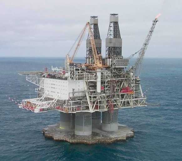